| Current Setting (A) | Measured Welding Current (A) | Measured Supply Current (A) |
|---|---|---|
| 105 | 60 | 20 |
| 225 | 120 | 29 |

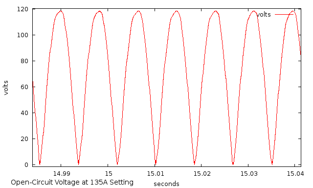
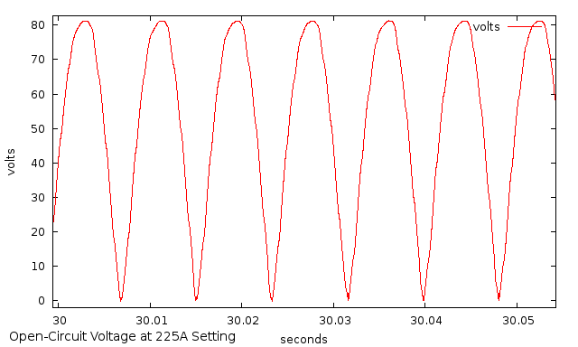
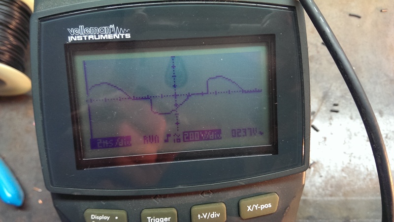
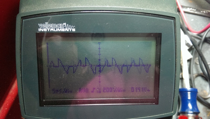
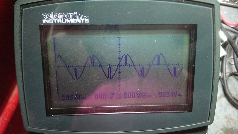
| Current Setting (A) | Measured VACrms | Measured VDCpeak |
|---|---|---|
| 135 | 83 | 118 |
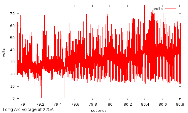
| 225 | 58 | 82 |
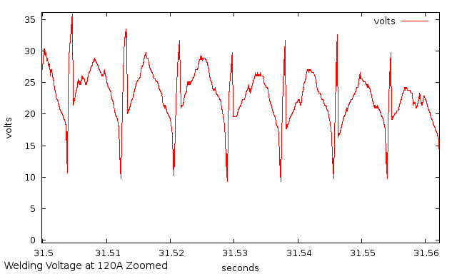
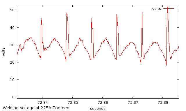
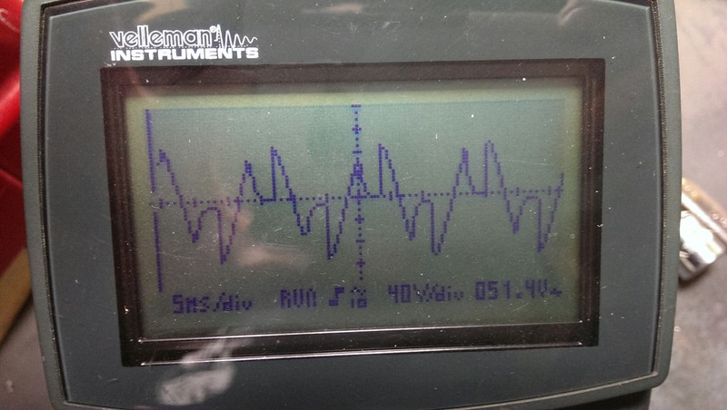
| Current Setting (A) | Measured VDCavg |
|---|---|
| 120 | 21 |
| 225 | 27 |
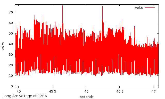
| Current Setting (A) | Measured VDCavg |
|---|---|
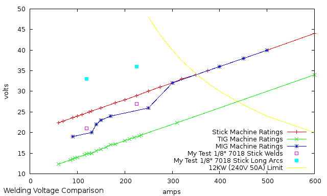
| 120 | 33 |
| 225 | 36 |
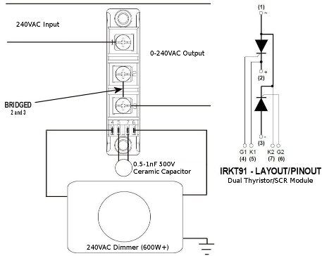
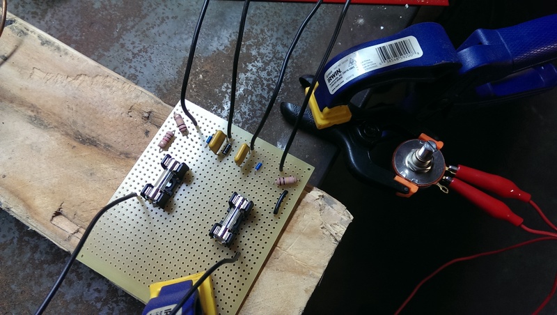
| Quantity | Part | Description |
|---|---|---|
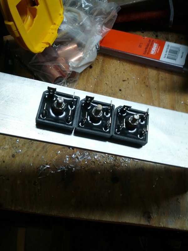
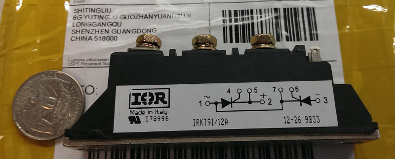
| 1 | IRKT91/12A | dual SCR/thyristor module |
| 2 | 1N4007FSCT-ND | diode 1KV 1A |
| 2 | 478-4045-ND | ceramic capacitor 0.1uF 1KV |
| 2 | DB3CT-ND | diac 28-36V 2A |
| 1 | RV4N254C-ND | potentiometer 250K ohm 2W |
| 1 | salvaged | potentiometer 470K ohm 2W |
| 2 | 100KZCT-ND | resistor 100K ohm 2W |
| 1 | 1KZCT-ND | resistor 1K ohm 2W |
| 1 | V2018-ND | pc board 0.1"sp 3x3.5" |
| 2 | 486-1258-ND | fuse block cartridge 500V 10A |
| 2 | 486-1848-ND | fuse 1.6A 125V 5x20 glass |