2009 Buell 1125R Voltage Regulator Upgrade
Introduction
FH012AA
Fried Stator
CE-605 SB
CE-605 SB Oscilloscope Results
Introduction
The 2009 Buell 1125R has problems with overheating stators right out of the factory. The high electrical load from lights and radiator fans coupled with inadequate stator cooling tends to melt the insulation and short the stator windings out over time. This means that battery charging capability slowly decreases over time until the bike fails to start or run completely. Buell/Harley's cheap "fix" for this issue was to install a wiring harness with a relay that would switch off one of the stator phases under certain conditions to reduce heat in the stator. This harness introduces more failure points, reduces charging voltage, and does not fix any existing stator damage. I noticed my charging voltage dip down into the high 12V range for significant amounts of time and the bike had trouble starting afterward, which is not acceptable. I removed the free harness and decided that a much better way to reduce the heat load in the stator is to reduce the electrical load on it.
FH012AA
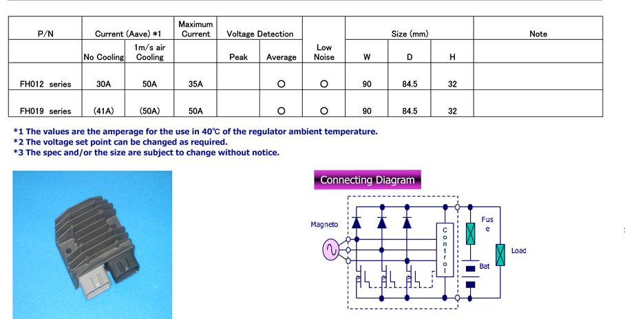
I decided to upgrade the voltage regulator from the stock shunt-type voltage regulator to a MOSFET-type regulator, which is much more efficient. I decided on the Shindengen FH012AA, which is the stock part on some other motorcycles. The normal shunt-type regulators always draw the entire 12V electrical current from the stator even though they waste any excess voltage as heat in the regulator. Initially, I thought the FH012AA MOSFET-type regulator switched individual stator phases off when there is excess voltage, which I now know is incorrect. The FH* MOSFET-type regulators are just more efficient at shorting stator phases out than a normal shunt regulator. A true series or switching regulator like Compufire or Cycle Electric, opens stator phases on over-voltage. This reduces the average current drawn from the stator, which should reduce stator heat and maintain full battery charge.
Installation was very straight forward and the kit from Roadstercycle.com linked above is excellent. After installing the kit, I got 14.5V at cold idle, which gradually decreased to 14.1V as the bike heated up to 190. While riding, the voltage ranges from 13.9V to 14.5V depending on temperature and RPM, which is certainly better than before.
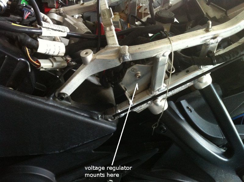
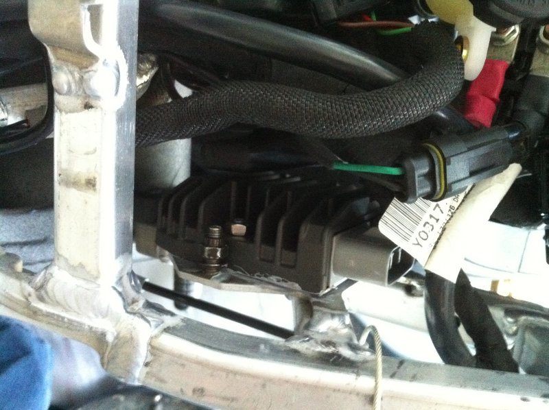
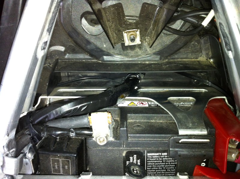
Here is where the voltage regulator mounts inside of the seat sub-frame.
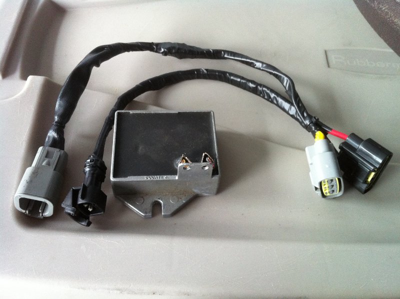
Here is the original voltage regulator, strangely a Ducati part, with its wiring removed and connected to the kit connectors. If I were doing this again, I would leave a few inches of wire connected to the original regulator in case I ever wanted to reuse it.
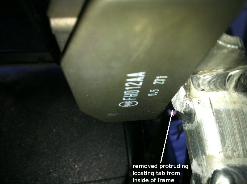
This shot shows where I had to remove a small locating tab with a tiny Dremel cutoff wheel in my cordless drill. The new regulator has slightly different dimensions than the original, but there is plenty of room for it.
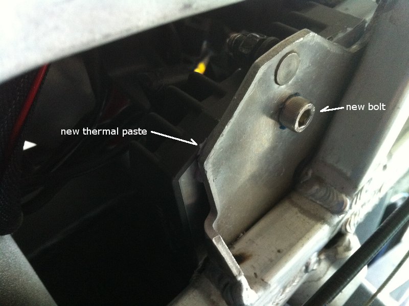
I used new non-conductive thermal paste (Arctic MX-4) and drilled a new top bolt hole in the mounting plate. The bottom stud fits if you use just the nut without the original washer. I coaxed the mounting plate flatter with a small hammer.
It's tight, but it does fit. If you can't get it to fit, try reversing it so the connectors do not interfere with the small fuse box. I had to trim a small amount of plastic from the under-tail panel to get it back in place and allow for airflow over the new regulator.
Fried Stator
About 1000 miles later, my stator died. Now I find out that the FH012AA is still a shunt-type regulator, just more efficient than the factory one. So, this regulator probably did nothing to extend the life of my stator. A better move would have been to use a Compufire or Cycle Electric series or switching regulator. Here is a nice install thread with a very important note: "Bottom line - if your model (across the board) has rare instances of Stator failure, the MOSFET units are ideal replacements. But if your models suffers from high incidence of stator failure, a Series R/R like the Compufire may be another choice." Here is an excellent experiment comparing the two types of regulators and here is a related thermal image.
CE-605 SB
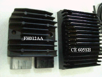
So, I decided to upgrade again to a Cycle Electric CE-605 SB series rectifier regulator with another kit. This one should properly limit current though the stator and therefore heat in the stator. I am installing this at the same time I am rewinding the stator and modifying the rotor on my Buell 1125R. If weight is any indication of build quality, the CE-605 SB is going to outlast the Buell. It is a good bit larger and heavier than the FH012AA. The easiest and least intrusive mounting location I found was just below the stock rear fender extension that holds the turn signals and license plate. It will not interfere with wheel travel or passenger foot pegs and it will be far from engine, radiator, muffler, and oil cooler heat. There is a decent air path for convection cooling while stopped and it should get plenty of air flow while moving. I secured it with four black UV-resistant cable ties and backed that up with black 550 parachute cord; sometimes the simplest solution is best. I drilled a hole under the tail for the wires, cut the connections to the FH012AA, and spliced in the CE-605 SB. I left the FH012AA in as a spare.
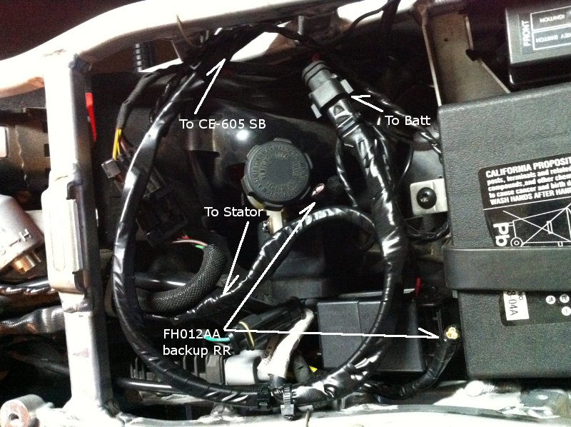
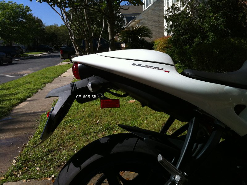
I did some hot idle testing as part of my stator rewind. I idled the bike in various states for about an hour. The results were promising. After an hour of idling, the regulator was pretty hot. I did not take a direct temperature measurement, but I could only touch it for 1-2 seconds, which works out to around 70C or 160F. It was definitely cooler than boiling, 100C or 212F, which is a safe operating temperature for many automotive electronic components like diodes and transistors. So, there should be enough convection back there to keep it running safely during long idle sessions. Even a small amount of air movement from inching up in traffic would help reduce its temperature. Mounting the regulator near the oil cooler does not seem like the best idea to me. During my testing, I could not touch the side of the oil cooler for more than a tiny fraction of a second, so uninsulated mounting there would be bad. Also, a lot of the radiator air is blown down while stopped, which heats up the area in front of and beside the oil cooler. It would be fine as long as the blown air temperature is less than the convection-only regulator temperature where I currently have it mounted. Here are the results with my rewound stator, drilled rotor, and the regulator mounted under the rear fender extension:
| time |
coolant
temperature (F) |
gear |
high beams |
rpm |
voltage |
| 12:49 |
159 |
n |
y |
1600 |
14.3 |
| 12:54 |
179 |
n |
y |
1500 |
13.6 |
| 13:02 |
193 |
n |
y |
1300 |
12.4 |
| 13:10 |
199 |
1st |
y |
1700 |
13.6 |
| 13:12 |
200 |
n |
y |
1300 |
12.3 |
| 13:19 |
208 |
n |
y |
1300 |
12.1 |
| 13:24 |
208 |
1st |
y |
1700 |
13.2 |
| 13:31 |
209 |
n |
y |
1300 |
12.1 |
| 13:33 |
209 |
1st |
y |
1700 |
13.2 |
| 13:34 |
209 |
1st |
n |
1700 |
13.8 |
| 13:35 |
209 |
n |
n |
1300 |
12.6 |
| 13:49 |
209 |
n |
n |
1300 |
12.6 |
|
|
|
|
|
|
Next, I went for a 30 mile cruise. It was mostly 20-45 mph with only a few miles of highway in the middle. I sat through probably 15-20 stop lights. The ride finished with about a mile at 20 mph. Ambient air temperature was about 80 F. The voltage never dipped below 13.8 even at the longest stop light. Most of the time it was between 14.1 and 14.5. The voltages would probably be a bit lower if the air temperature was above 100 F. As soon as I pulled into the garage, I stopped the engine, removed my gloves, and felt the CE-605 SB regulator temperature. It was warm, not hot; I could grab the regulator continuously with my hand or press my inner forearm against it continuously, which works out to less than 45C or 113F. I think the mounting location I chose for the new regulator is great.
CE-605 SB Oscilloscope Results
I connected channel 1 of my Rigol DS1052E across two stator leads to see what happens to the stator lead voltage at idle and when the series regulator is actively regulating at higher rpm. No dual-probe differential input is necessary since the motorcycle was totally isolated from ground. Here are two shots at idle, 200F coolant temperature, both fans running, and 12.5V battery voltage:
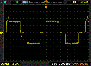
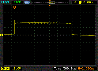
Here is a shot at 4000 rpm, 185F coolant temperature, both fans running, and 14V battery voltage:
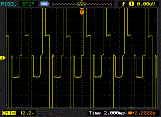
Here are additional files in case someone wants to create bigger plots from the data:
ce605sb-idle1.txt
ce605sb-idle1.csv
ce605sb-idle1.wfm
ce605sb-idle2.txt
ce605sb-idle2.csv
ce605sb-idle2.wfm
ce605sb-4krpm.txt
ce605sb-4krpm.csv
ce605sb-4krpm.wfm


