| time | coolant temperature (F) | gear | high beams | rpm | voltage |
| 12:49 | 159 | n | y | 1600 | 14.3 |
| 12:54 | 179 | n | y | 1500 | 13.6 |
| 13:02 | 193 | n | y | 1300 | 12.4 |
| 13:10 | 199 | 1st | y | 1700 | 13.6 |
| 13:12 | 200 | n | y | 1300 | 12.3 |
| 13:19 | 208 | n | y | 1300 | 12.1 |
| 13:24 | 208 | 1st | y | 1700 | 13.2 |
| 13:31 | 209 | n | y | 1300 | 12.1 |
| 13:33 | 209 | 1st | y | 1700 | 13.2 |
| 13:34 | 209 | 1st | n | 1700 | 13.8 |
| 13:35 | 209 | n | n | 1300 | 12.6 |
| 13:49 | 209 | n | n | 1300 | 12.6 |
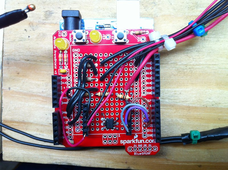
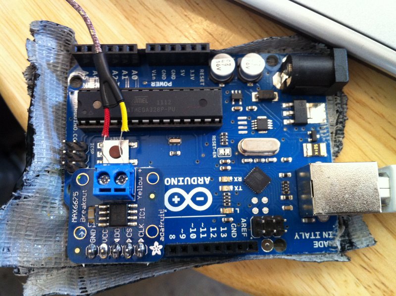
| Part | Sparkfun Part Number | Unit Price |
| Arduino Uno | DEV-11021 | $29.95 |
| Arduino ProtoShield Kit | DEV-07914 | $14.95 |
| Thermocouple Type-K | SEN-00251 | $13.95 |
| Thermocouple Amplifier Digital MAX6675 | COM-00307 | $11.95 |
| SOIC to DIP Adapter 8-pin | BOB-00494 | $2.95 |
| Thermistor 10K | SEN-00250 | $1.95 |
| 9V to Barrel Jack Adapter | PRT-09518 | $2.95 |
| Total w/o shipping, resistors, & wire | $78.65 |