Electric Arc Furnace (aka Carbon Arc Furnace)
Introduction YouTube Playlist Welder Cutting Metal Frame Linear Bearing Stepper Motor Actuator Electrode Jaws Electrode Arm Cooling System Control System Source Code Crucibles Refractory Crucible Tongs Power and Efficiency Remote Monitoring Molding Sand Preheat 2018 CSME National Design Competition Assistance
Introduction
An Electric Arc Furnace (EAF), aka Carbon Arc Furnace (CAF), melts metal with an arc between movable carbon electrodes and the charge metal in a conductive crucible. Most EAF articles and videos I have seen describe three-phase megawatt-scale equipment used at recycling plants. These industrial-size EAFs use three carbon electrodes and special power feeds from the power company; definitely out of reach for most hobbyists. I have seen many videos on Carbon Arc Gouging (CAG) with large, but attainable, welding equipment. Between these two ideas and my mostly failed look into induction , I thought a garage-scale 240V single-phase EAF would be a very interesting DIY project. I thought an EAF would be simpler and more flexible than an induction furnace, while still being capable of melting steel and aluminum for casting. The main down sides are carbon contamination, carbon consumables, and limited metals. A small EAF should be much more efficient than a gas or liquid fuel furnace since it doesn't need high air flow.Grant Thompson - "The King of Random" and AvE - "Arduino vs Evil" . Both of these guys did some small hand-held carbon arc melting and casting in late 2014. Thank you.YouTube Playlist
VIDEO
Welder
Welding a few inches at a time is a lot different than melting 10+lbs of steel in a single run. An EAF requires high current and high duty cycle. I sold my modified Lincoln AC-225 and purchased an Everlast PowerARC 300 . That didn't work out, so I sold it and upgraded to my Lincoln Invertec V275-S . It supports 200A at 100% duty cycle and it actually does what the spec sheet says. Also, I should be able to parallel two of them if 200A proves insufficient.Cutting Metal
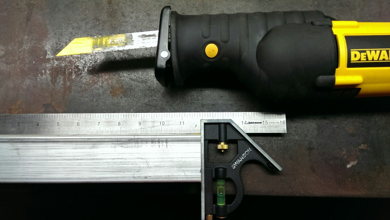
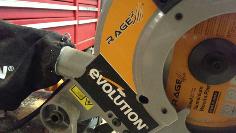
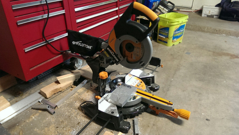
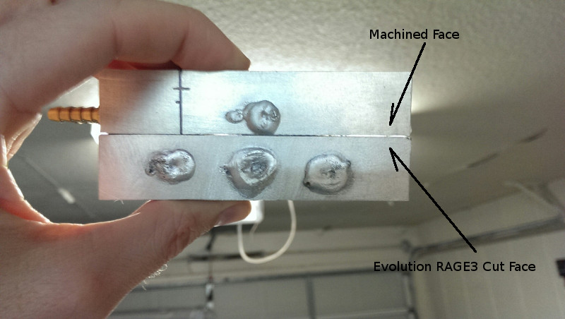
I decided to make the EAF frame out of aluminum. I thought it would be a lot lighter than steel and corrosion resistant. I have used my 4.5" angle grinder in the past, but getting cuts square and even is pretty difficult. I started with a reciprocating saw. If I was careful and slow enough, I got pretty good results, but I wasn't fast or consistent.Evolution RAGE3 10" TCT Multipurpose Sliding Miter Saw. I got the single bevel version, which is cheaper and direct drive with no belt to wear out. The motor is lower RPM than wood miter saws, which allows using TCT blades on metal. It lives up to its claims and I'm very happy with it. After initial squaring, the cut quality and angles are pretty good. As an added bonus, it seems to be a half decent wood miter saw too. The stock blade has 28 teeth and I haven't had any problems cutting wood or aluminum with it. I also picked up a 52-tooth dedicated steel cutting blade, but I haven't had a need to try it out yet.Frame
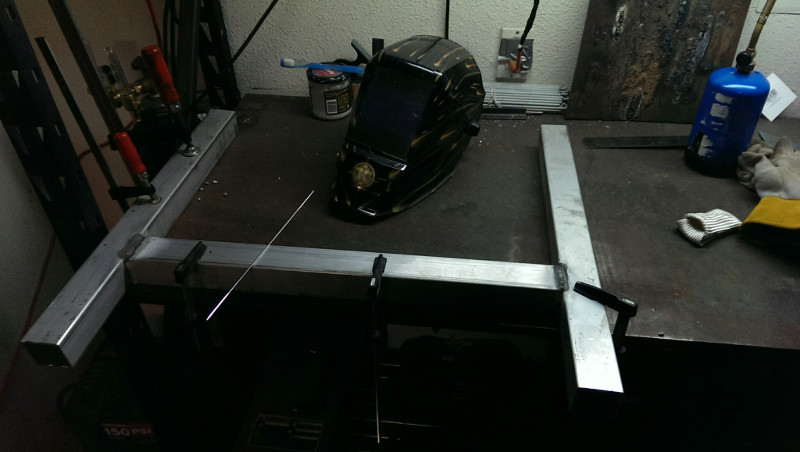
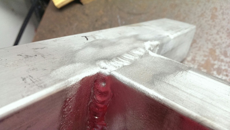
I used 2" 0.125" wall 6061-T6 aluminum square tube for the frame. I started welding it using DC TIG with argon and flux . Then I got tired of the prep work and the cleanup. I got impatient and started using aluminum stick electrodes for some of it. The vertical rail bolts on with 5/16" stainless hardware and the adjustable feet are 5/16" bolts threaded into the aluminum tube. Three important tips:
Check square tubes for twist after checking for straightness.
Don't assume your welding table is perfectly flat.
More clamps is almost never a bad thing.
Linear Bearing
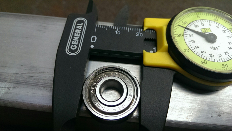
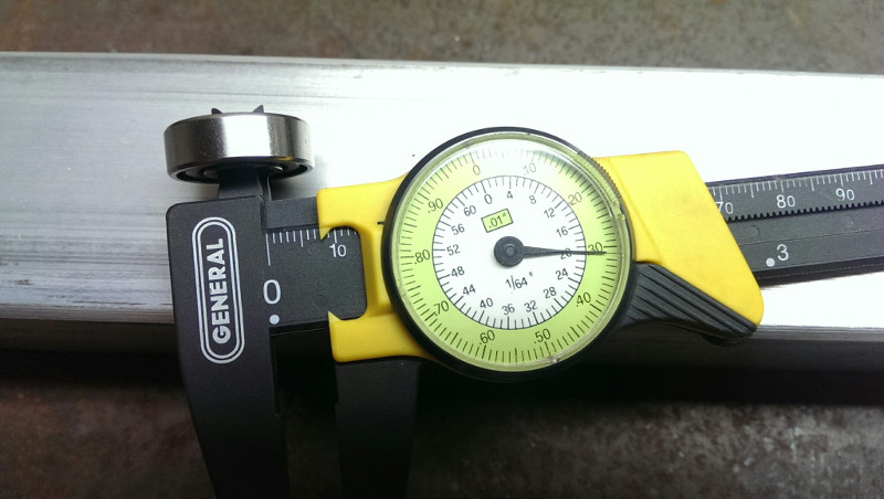
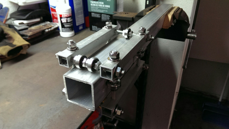
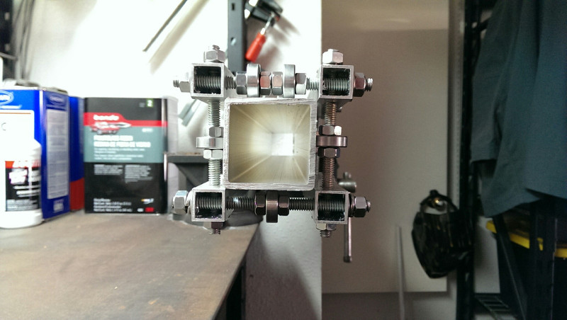
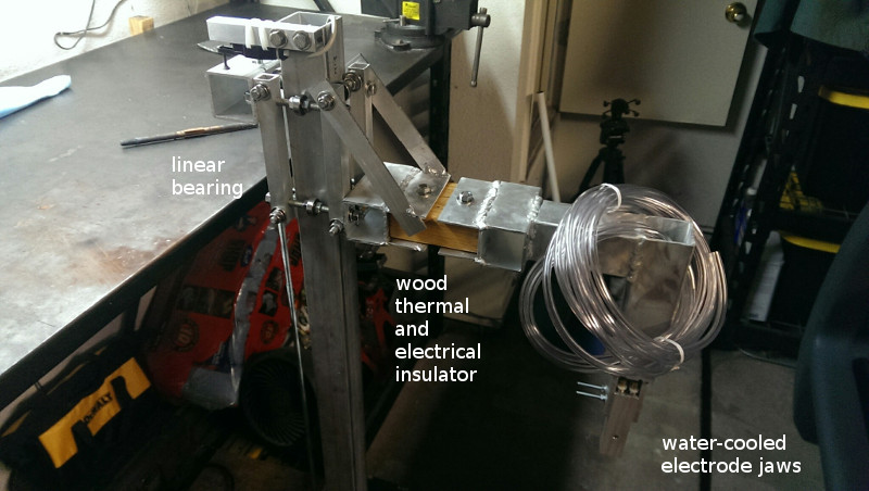
I only found two good pages or videos that discussed a linear bearing for square tube. Both were pretty half baked, but they got the idea across. I used BSB ABEC 9 skate ball bearings, 5/16" fasteners, and 3/4" 0.0625 wall aluminum square tube to make a linear bearing for square tube. With this arrangement, the square tube must be smaller than the diameter of the skate bearings to clear the rail. I drilled two outboard through holes on one tube face and two inboard through boles on the other face. That made sure all 4 tubes were exactly the same. Access to a drill press comes in handy when being square and accurate is important. Otherwise, you'll have to do very careful layout and punch marks on all sides of the part. Red thread locker is handy for making custom bolts from threaded rod and nuts.Stepper Motor
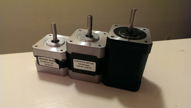
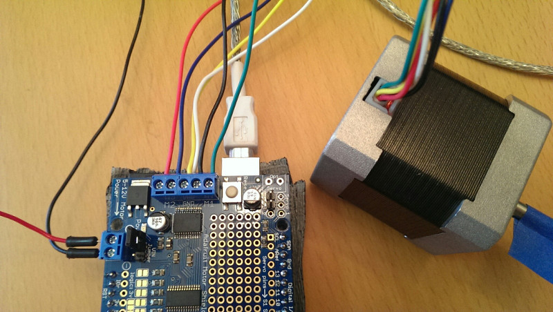
The first stepper motor I bought did not have enough torque for this project. The second had enough torque for painfully slow operation. The third was better, but still on the slow side because of the high threads per inch (TPI) on my threaded rod actuator. It is a Nema 17 Unipolar Stepper Motor 65Ncm(92oz.in)1.2A 17HS24-1206S . A lower torque stepper might work well and give reasonable speed with a belt and pulley setup instead of the threaded rod approach I chose, but I don't feel like redoing things just to find out.Actuator
I chose to use 5/16" 18TPI threaded rod as my linear actuator since I had a lot laying around after building the linear bearing. The fine pitch makes for pretty slow operation, but it should be able to handle a good amount of weight. I simply tapped threads into a piece of aluminum square tube to ride on the threaded rod and attach to the linear bearing. I found a 5mm (stepper shaft) to 8mm (threaded rod) flexible aluminum coupler on Amazon, marketed for the RepRap 3D printer.Electrode Jaws
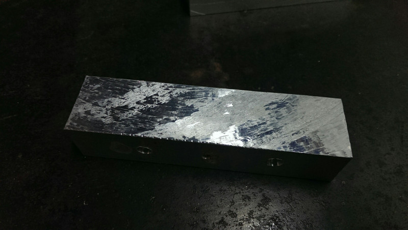
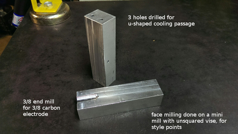
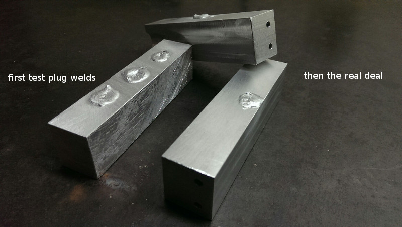
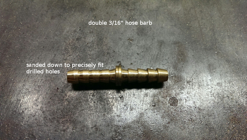
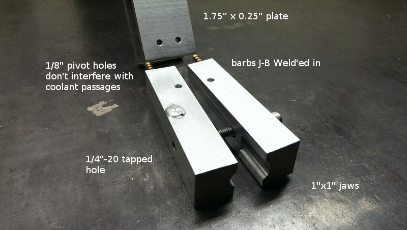
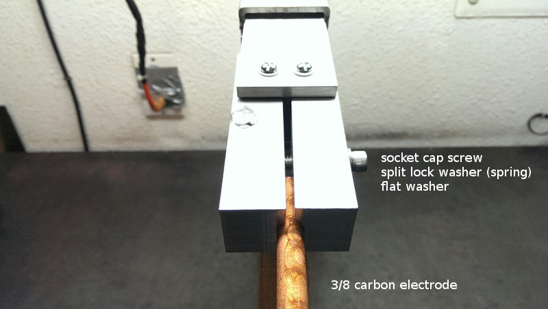
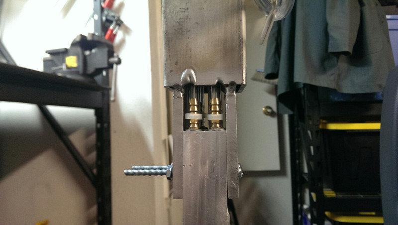
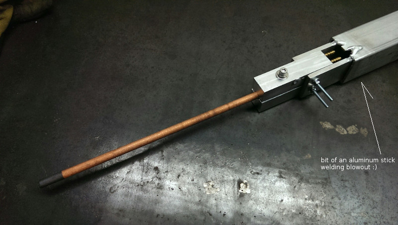
I chose to make water-cooled aluminum electrode jaws for holding the carbon electrode. I cut a few 1"x1"x5" pieces from 1"x5"x9" plate with my TCT saw. Luckily, my friend Chris has a mini mill, which worked great for face milling the rough cuts, drilling all of the holes, and milling the cylindrical electrode contacts. I drilled three holes to form a u-shaped cooling passage in each jaw. I plug welded the third hole to convert from a 3-opening F-passage to a 2-opening U-passage. I used 3/16" hose barbs and 3/16" hose for plumbing. After sanding one end of the barbs for precise fit, I used J-B Weld to permanently install them in the jaws. After that, some carefully drilled 1/8" pivot holes and clamp holes completed the drill press work. I hand drilled and tapped one of the clamp holes 1/4-20 and hand drilled the other for clearance. I used a 1/4-20 socket cap screw and a split lock washer as the electrode clamping mechanism. The lock washer provides sufficient tension. Carbon electrodes are brittle, so be careful to not over tighten.Electrode Arm
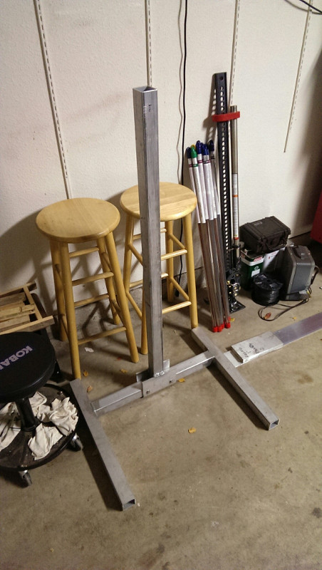
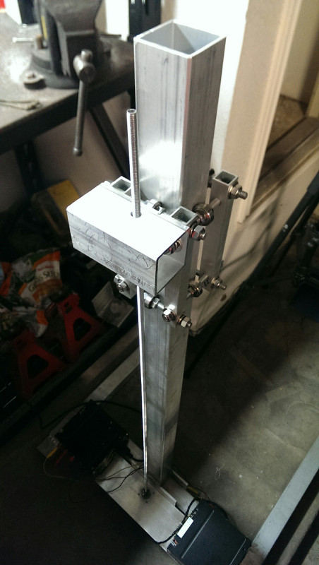
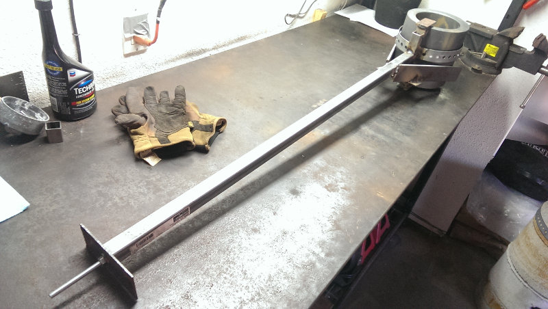
I made the electrode arm mostly using 2" square tubing left over from building the frame. For the bottom two linear bearing attachment holes, I measured the threaded rod distance with dial calipers with the linear bearing installed. Then careful marking, punching, and drilling made for a pretty exact fit. The holes are a tad oversize for the threaded rod for a little wiggle room. I drilled the two gussets, installed them on the top threaded rod, and then welded them with everything in place and supported. This resulted in zero slop. Notice that the arm is connected to linear bearing bolts on the front and sides. This arrangement provides good vertical and lateral stability. With everything just finger tight, there is only a tiny amount of play in the vertical direction from the flexible aluminum shaft coupler where the threaded rod meets the stepper motor. The wood 2x4 link provides thermal and electrical insulation.Cooling System
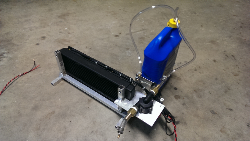
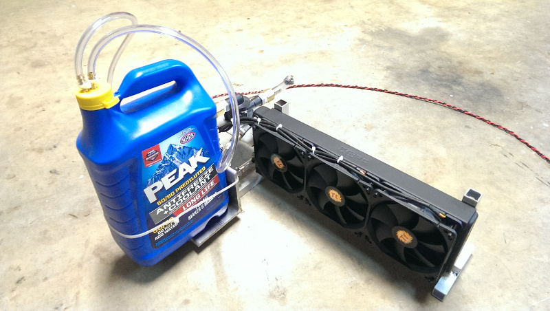
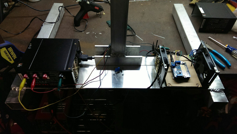
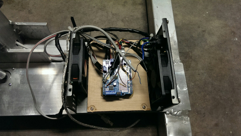
I chose an XSPC EX360 radiator , three Thermaltake 120mm fans , XSPC G1/4" to 3/8" barb fittings , and a US Solar Pumps 12V 3GPM water pump for my water cooling system. Lowe's provided plumbing fittings and tubing. I welded the frame from the same 3/4" 1/16" wall aluminum square tube as the linear bearing The fans are pretty quiet compared to other stuff in the garage; I was surprised. I thought about using the Arduino as a thermostat for the fans, but decided against it because more sensors and wires seemed unnecessary at this point. Maybe I'll try that approach when I get around to a DIY TIG water cooler.Control System
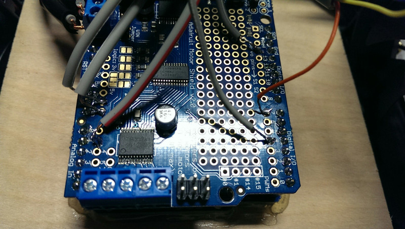
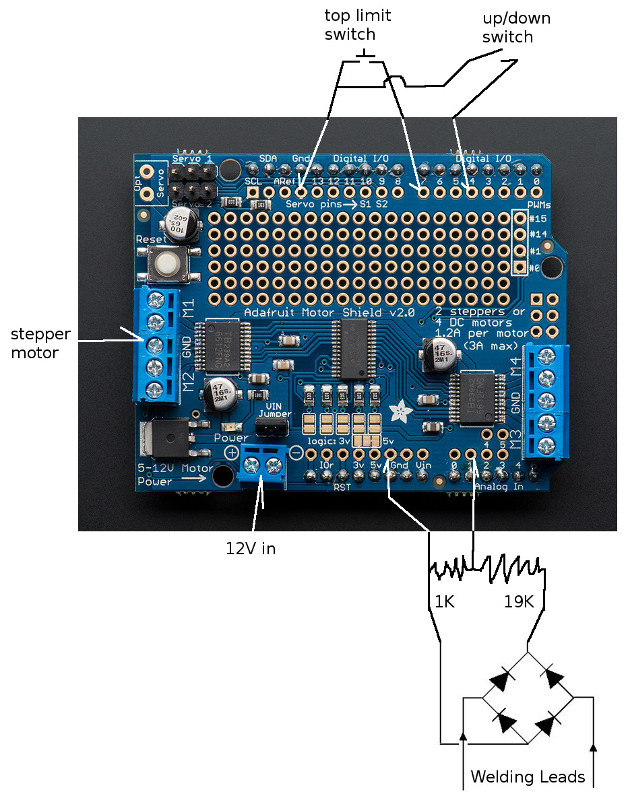
I used an Arduino Uno and an Adafruit Motor Shield V2 as the brains of the control system. Power and project enclosure came from two ATX PC power supplies. An upper limit switch came from a spare TIG torch switch. The up/down switch was the power switch in the second power supply enclosure. The analog input is fed by a voltage divider for voltage protection and a bridge rectifier for reverse polarity protection. I welded a 4"x0.25" plate to the base of the frame to mount the power supply, microcontroller enclosure, and stepper motor.Source Code
The source code for this project comes in three parts:
The Adafruit Motor Shield V2 Library .
A patch to the Arduino library: eaf_arduino_patch.txt
The Arduino sketch that ties it all together.
Crucibles
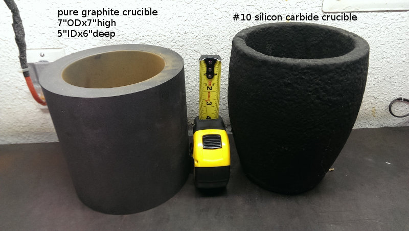
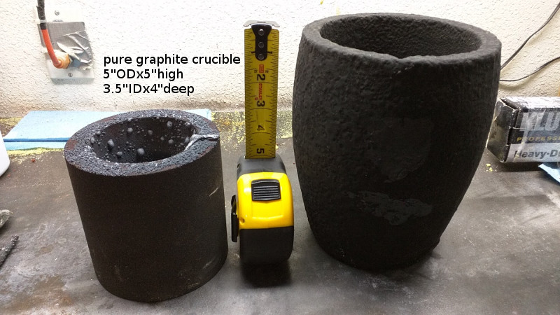
My plan involves a single carbon electrode and a conductive crucible. Clay/graphite and silicon carbide/graphite crucibles are not conductive enough to use as part of an electric arc furnace's circuit. Their electrical resistance is just too high to be used at welding and gouging voltages. A pure graphite crucible works great. The only other solutions I could think of were to embed a carbon rod in a DIY ceramic crucible or just place a second rod in the crucible touching the base metal. My silicon carbide crucible came from Legend Mine . My pure graphite crucible came from GraphiteStore.com . I may still use the SiC crucible if I experiment with a charcoal-fired furnace. The pure graphite crucible will be interesting to handle and pour from since it is rather cylindrical.Refractory
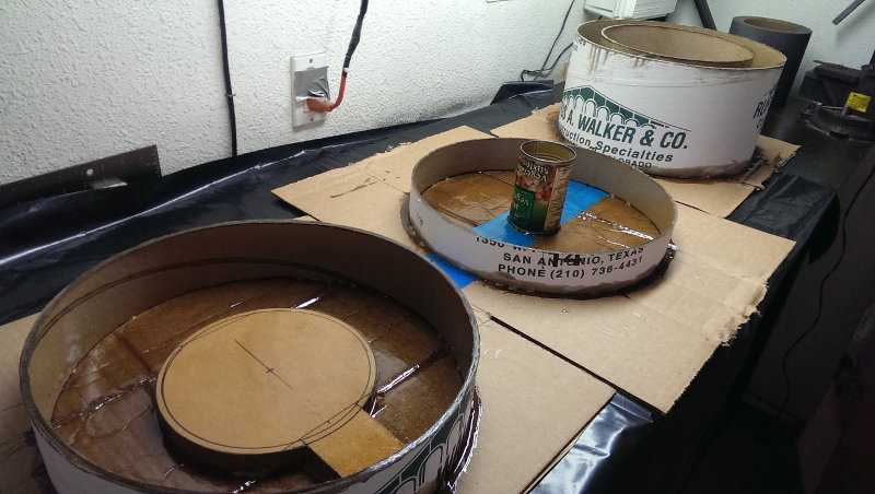
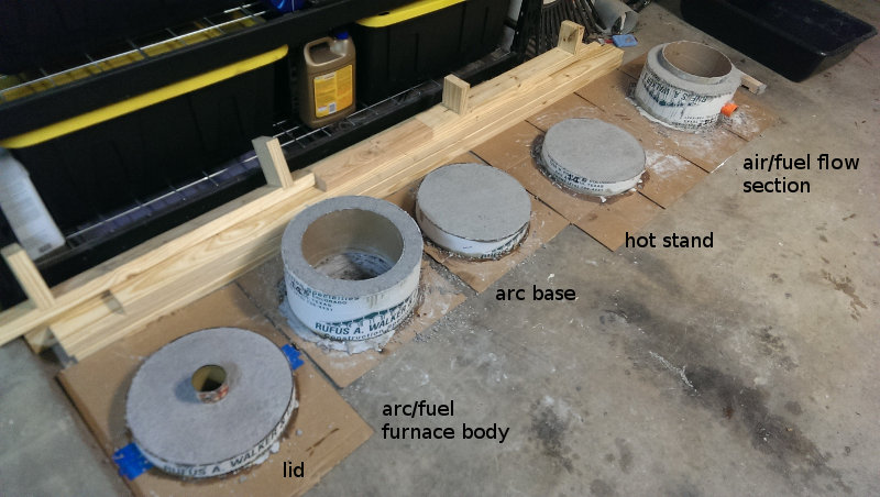
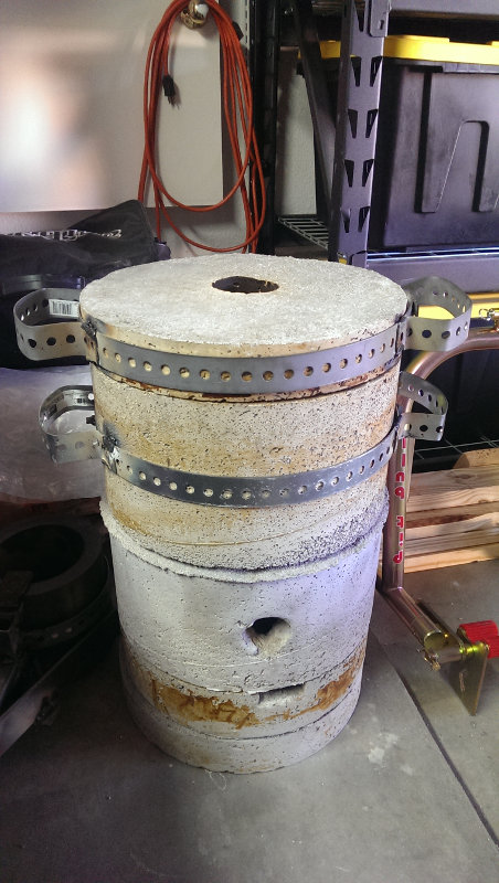
My first attempt at furnace wall refractory involved a suggestion from a friend and some internet searching. I bought alumina and kaolin clay from a local ceramic supply warehouse. I mixed up a very small batch to measure shrinkage and final density and I just about destroyed my forearms and hands in the process. That stuff is incredibly difficult to work by hand and I would like to finish the furnace body before the inevitable heat death of the universe. So, I switched gears and bought two 55-lb bags of 3000F Kast-O-Lite 30 LI castable refractory from Legend Mine. I bought some "14 inch" and "10 inch" concrete form tubes from a local supply place. Those dimensions were actually pretty rough. I ended up with about 1.5" between the forms and a section of 2x4 was perfect for tamping. I used hot glue to tack everything together and then put on a couple liberal coats of polyurethane for waterproofing. This stuff was a lot easier to work than the clay, but it was still pretty back-breaking work. It didn't exactly pour into the forms either. I filled them with a hand trowel and tamped it down little by little. I made two extra parts to use the remainder of the second bag. I made a short stand, nearly the same size as the furnace bottom, to set hot stuff on. I also made an air/fuel flow section in case I want to try some fuel-fired furnace or forging work. I realize the gap where the sections meet will not be air tight and this layout is not ideal for a fuel-fired furnace, but the furnace should be as small as possible for arc melting and the additional section adds some versatility. I followed the 100F/hour initial heat up to 500 in my oven and then I lit a charcoal fire in it.Crucible Tongs
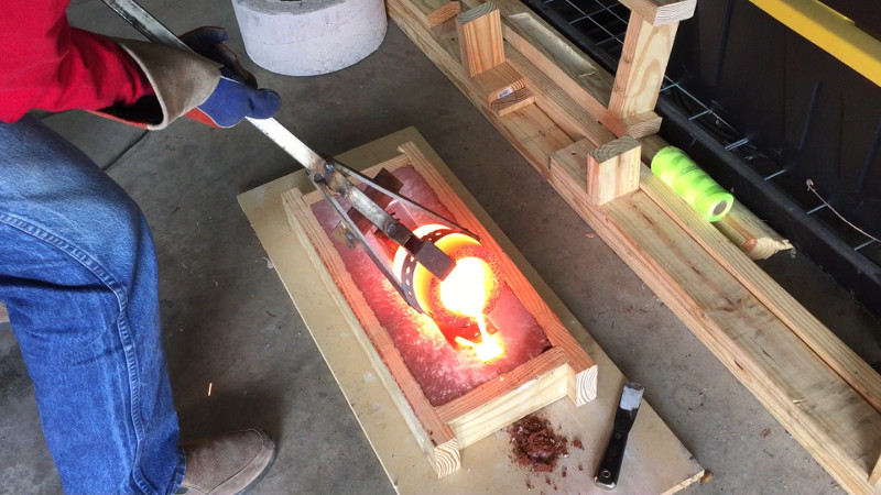
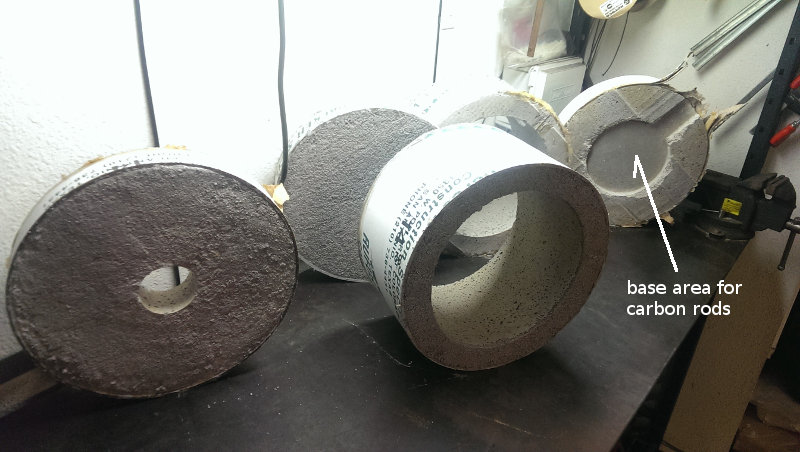
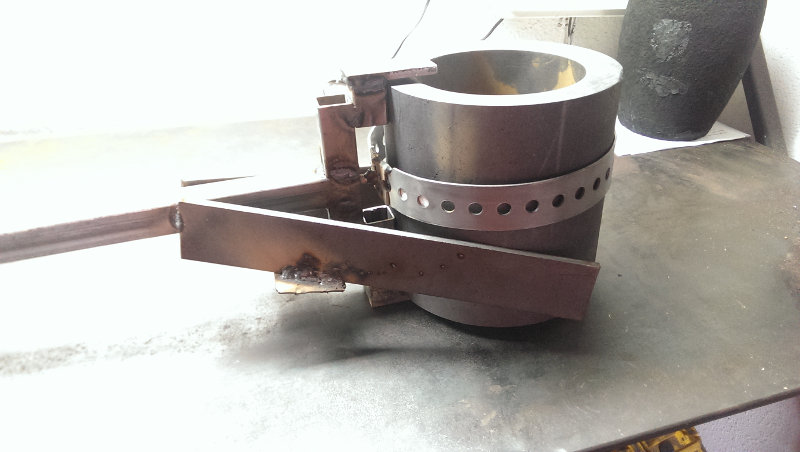
I have not seen crucible tongs for perfectly cylindrical crucibles before. All of the casting tongs I have seen have either been hot-dog size for jewelers' crucibles or something that takes advantage of the curved profile of something like the #10 SiC crucible I mentioned above. A crucible that gets wider at the opening seems like an easier geometry to grip securely because of its roughly wedge-shaped profile. Obviously, you can lift a heavy cylinder if you can pinch it tight enough. However, the lubricating and brittle nature of pure graphite made me want to try something other than just gripping it really tightly. I decided I would leave an inch gap in the carbon rods the crucible sits on at the base of the refractory. This left enough room for a lifting tongue to be inserted under the crucible, which greatly reduces the required grip pressure. Then it was just a matter of devising something that would hold it tight enough to keep it controllable. The following two photos show what I came up with. The circular metal band is lowered over the crucible. Then the nut is tightened on the threaded rod, which forces the lifting and retaining tongues over the crucible. When it is snug, the crucible is pulled into the vertical and lateral supports so it is restrained in every direction. My only concern with this approach is the relatively thin (1/16") band, which may deform or stretch with heat and load. This tong design requires the refractory furnace walls to be lifted off the crucible; the crucible cannot be lifted out of the furnace. The first test will certainly show if this setup is adequate.Power and Efficiency
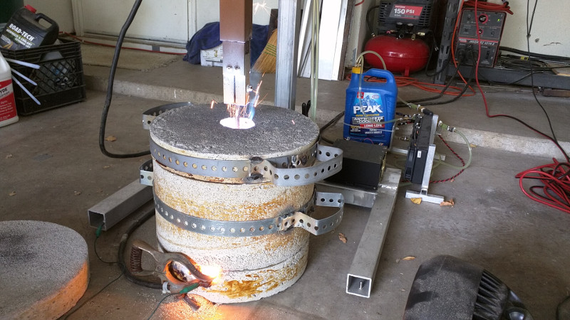
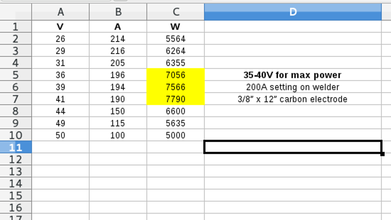
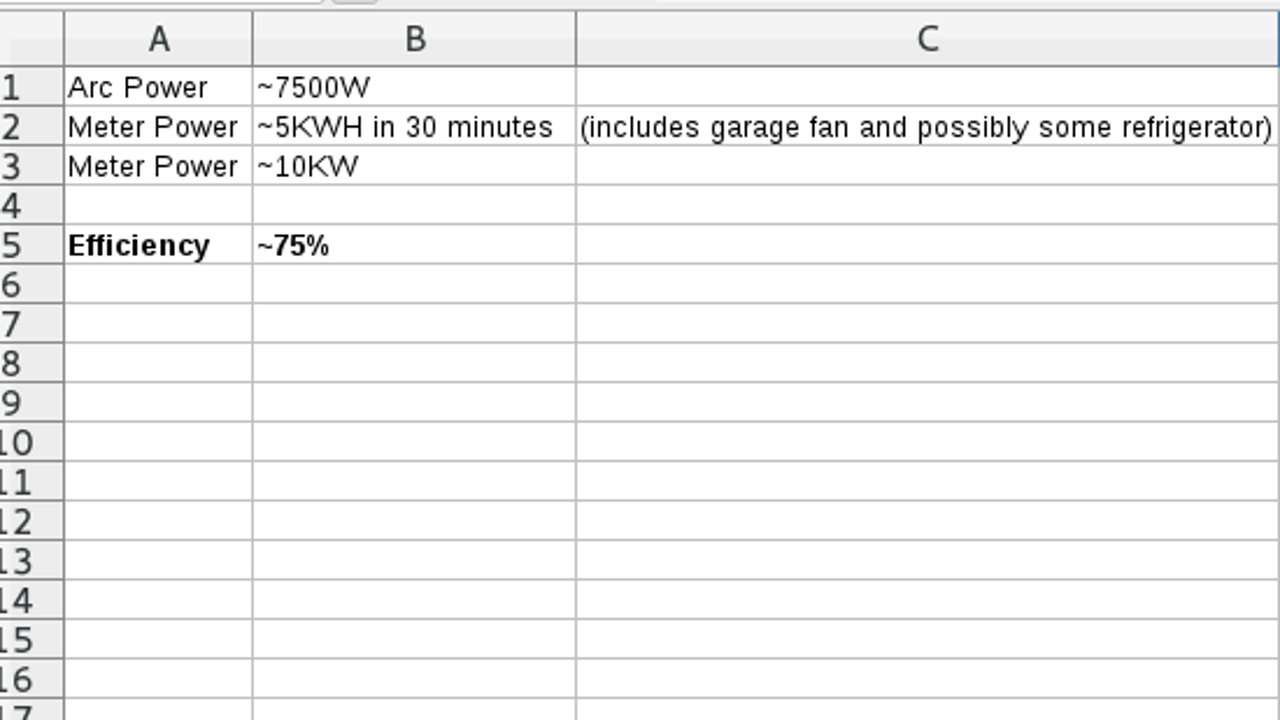
I hooked up my clamp-on current meter and my multimeter to get a rough recording of instantaneous current and voltage. I recorded the measurements from arc strike to long arcing. Afterward, I plugged some of the numbers into a spreadsheet to figure out a rough voltage range that should be close to maximum power output for my configuration and equipment. The optimum voltage range is around 35-40V. With the welder set to the maximum 100% duty cycle at 200A, the maximum power output range is between 7KW and 8KW. That is with the 3/8" x 12" carbon electrode. If the arc gets too long, high voltage range, the arc resistance shoots up and the current and power fall off. If the arc is too short, low voltage range, the power also falls off.Remote Monitoring
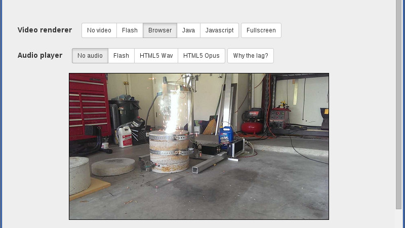
I used an old Android phone and the IP Webcam app to monitor things from the air-conditioned comfort of my living room. After the free IP Webcam app proved useful, I spent the couple bucks and upgraded to the IP Webcam Pro version.Molding Sand
I used Petrobond sand from Midwest Technology Products . It worked great in my initial testing.Preheat
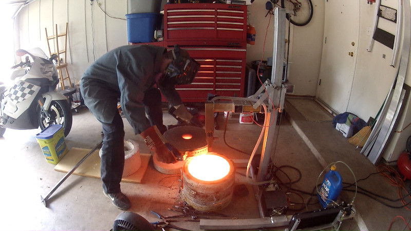
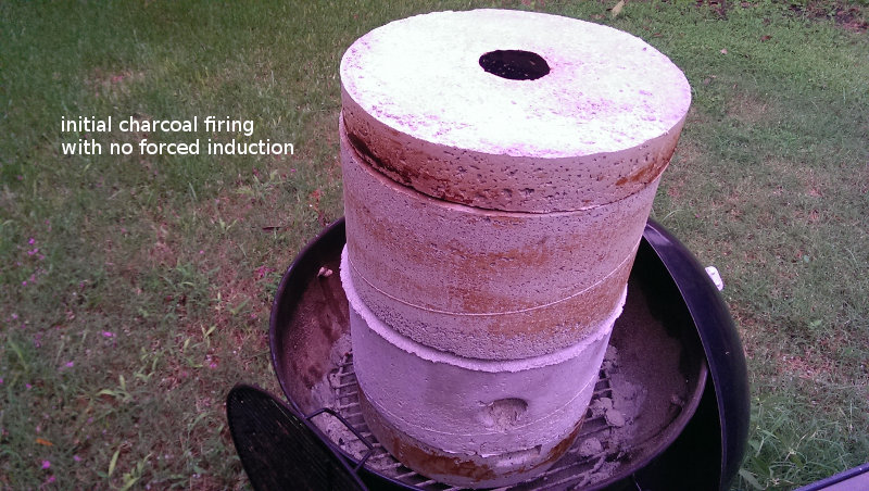
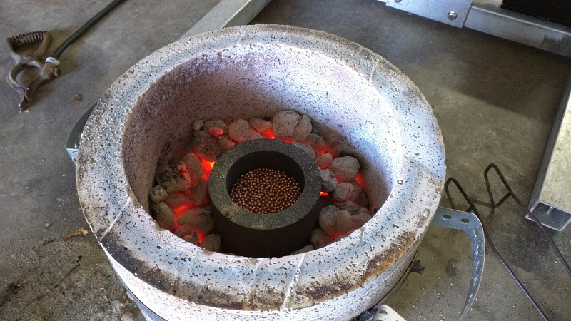
My first big melt with the 7" crucible was too big. I melted about 10 lbs of steel before my exterior 240V circuit breaker overheated. It was just too much current for too much time for my stock house wiring to handle. I switched to the 5" crucible, about half as much steel, and I decided to preheat with charcoal. I filled and lit my charcoal starter and then waited for all of the charcoal to ash over. Then I used tongs to fill the area around the crucible with hot coals. I put the lid on and let that preheat, without forced air, while I worked on the mold. The charcoal and ash also provided additional insulation between the crucible and the furnace body.2018 CSME National Design Competition Assistance
Michael Wladysiuk reached out to me via email in early 2017. He, and some fellow engineering students at Concordia University, wanted to build on my work as part of their capstone coursework. He politely asked permission to build on my arc furnace ideas, pick my brain from time to time, and reference my work. The result of his team's hard work was an entry into the 2018 CSME National Design Competition. I think they really knocked it out of the park. They took the welder-dc-arc-furnace idea, automated it, polished it, and really did a great job. Congratulations!ELECTRODE project page .final YouTube project video .