This project is a delta 3D printer design inspired by the Tevo Little Monster (TLM) and the Anycubic Predator (AP). This page is not affiliated with either company. Both sources of inspiration are larger delta printers that cannot be purchased in the US as of December 2020. After seeing the TLM and AP are both discontinued, I tried to purchase a Homers Hector/Little Monster, but no luck. After several months and zero email responses, I requested a refund. But I still wanted to upgrade from my excellent Prusa i3 MK3S + OctoPrint to a larger, faster, enclosed printer. That's what led to this project.
If my TLM purchase had been successful, I would have made several changes and upgrades. Lots of reviewers don't love the TLM out of the box, but many are very happy after making some modifications. This project is definitely more effort and more expensive than my original modified TLM/AP plan. But it gives me an opportunity to cut fewer corners, learn more, and use more top-shelf components.
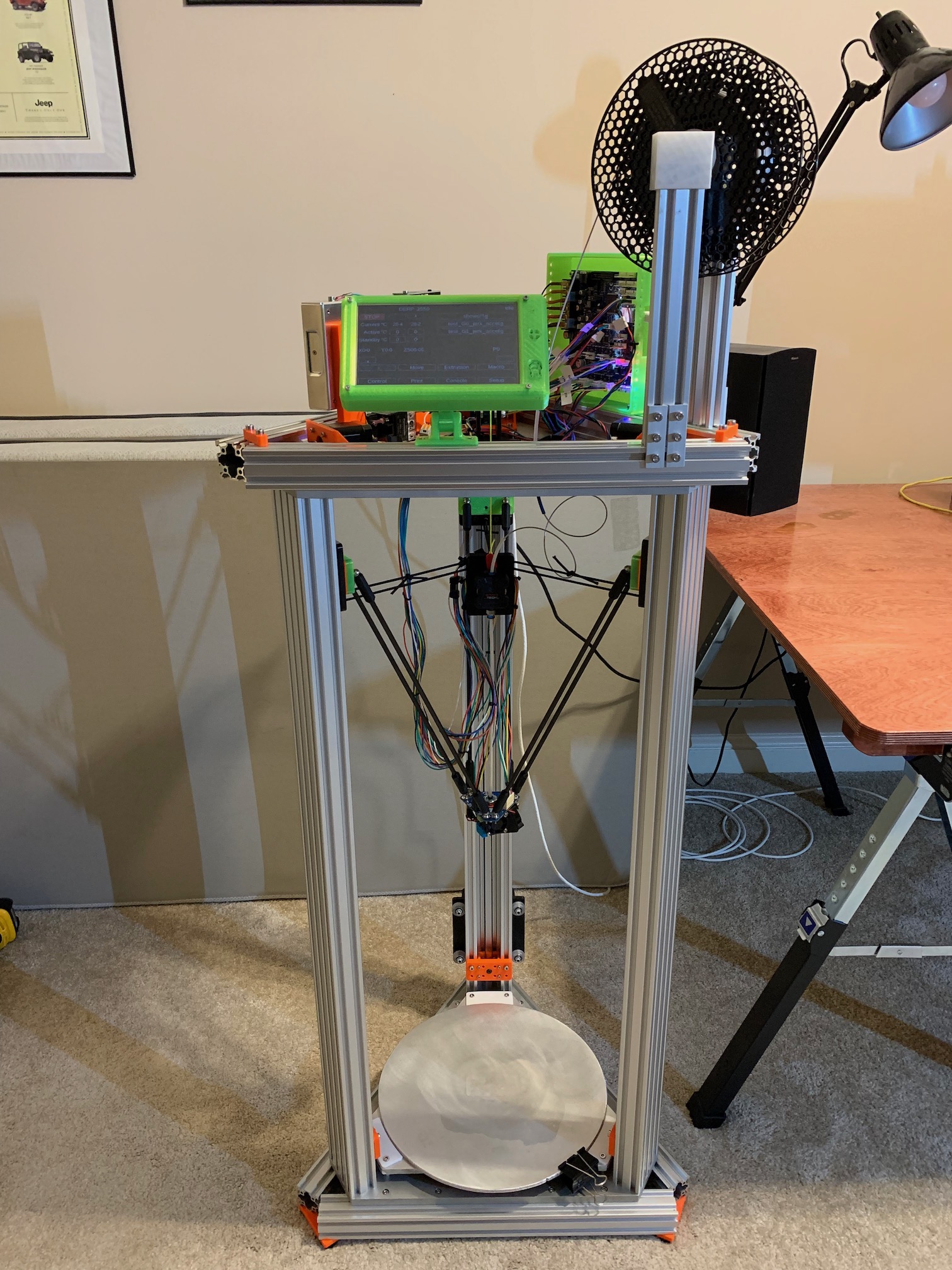
I'm dubbing this project DERP 3550, the:
I'll start with squirting hot plastic, but I'd eventually like laser beams and spinning sharp things mounted. The 3550 denotes the build diameter of 35cm and the build height of 50cm.
DERP 3550 by Gregory Alan Hildstrom is licensed under CC BY-SA 4.0![]()
![]()
![]()
I chose a TLM-like design, but with more overkill. This seemed simpler to construct than an AP-like design. The design has the advantage of low part count. But frame rigidity and accuracy are directly related to part quality and accuracy, with less room for adjustment. Squareness and rigidity of the frame are derived from a few critical areas:
For rigidity and flatness, I'm using thick standard plate for the top and bottom frame plates. Standard plate proved insufficient for the bed and build plates, so I'm using cast aluminum tooling plate for those. The as-delivered c-beams likely have a chopsaw or bandsaw cut edge. The c-beams I received were quite good, so I don't think the ends need to be milled or ground square.
Why not core-xy? First, I think deltas look cool AF. Second, my Prusa is cartesian and I want to try a delta to expand my horizons. Third, to extend a middle finger to Tevo, Homers, and Anycubic for making interesting products and then not continuing to produce or improve them.
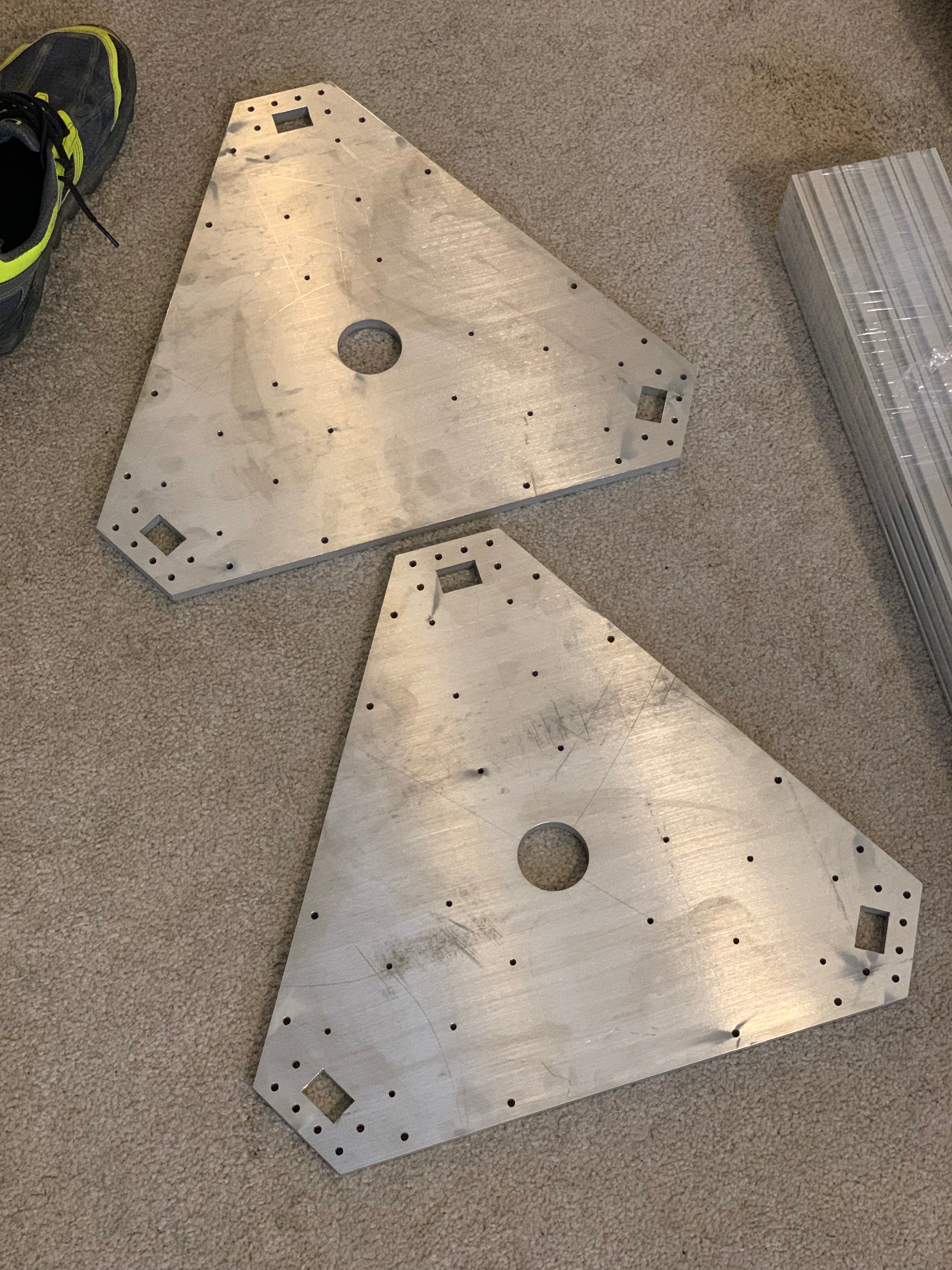
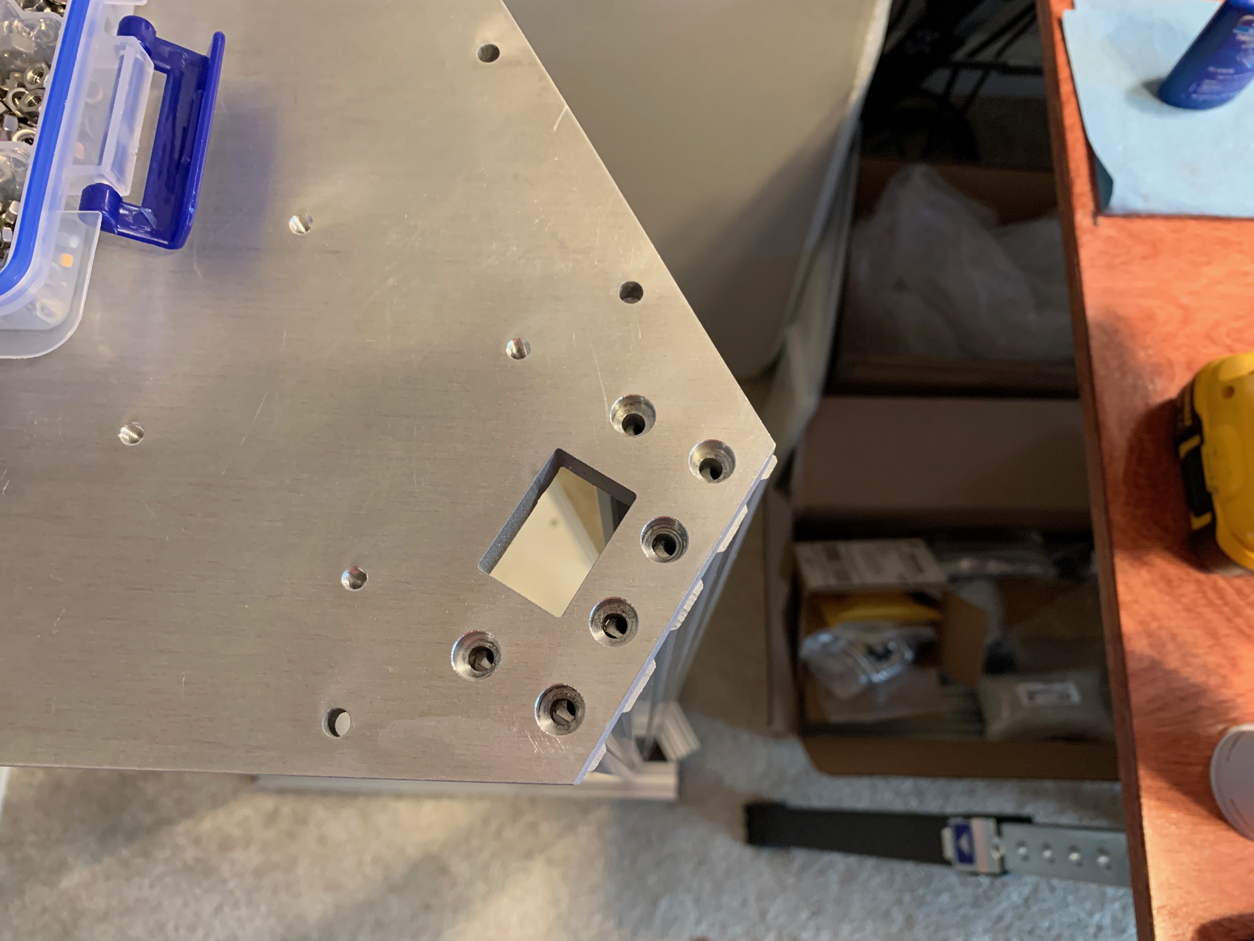
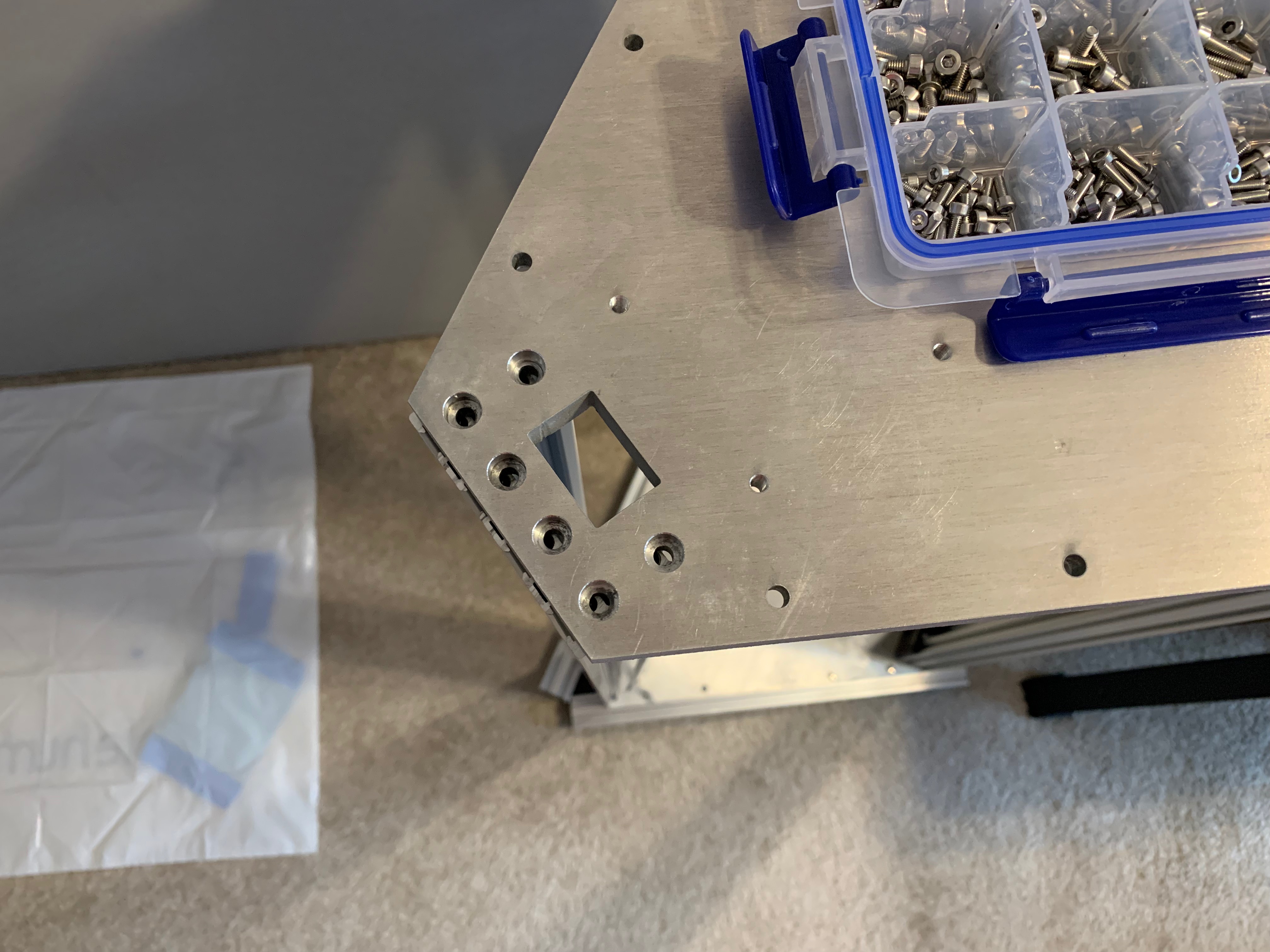
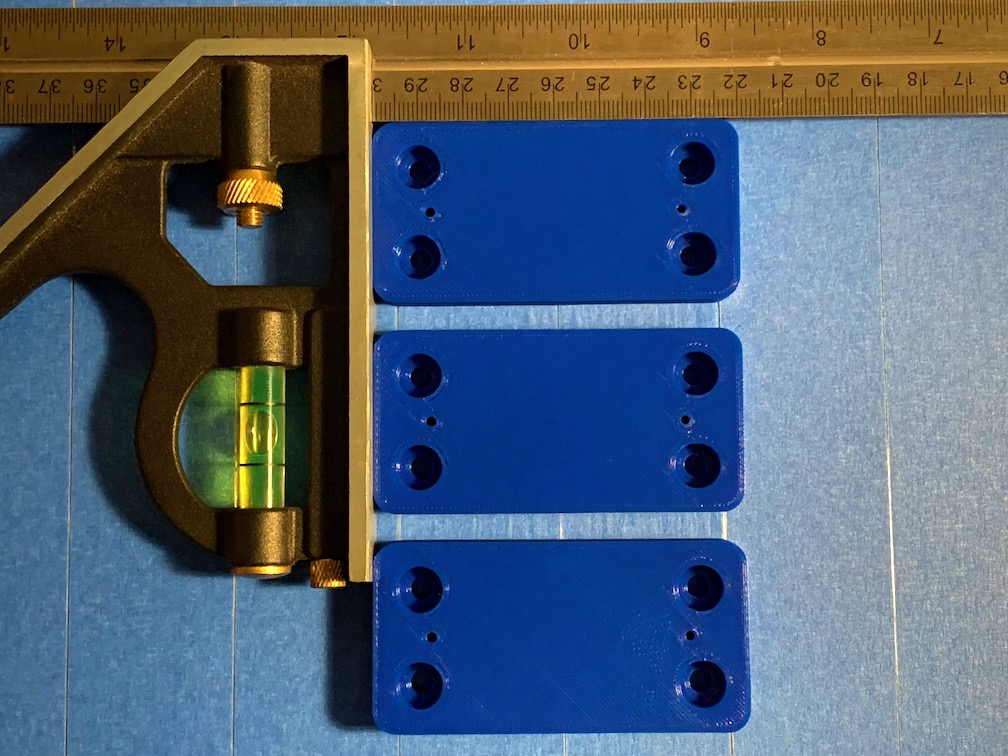
The hexagonal plates on the TLM look cool, but they make it more difficult to enclose. I reviewed some of the open source TLM models (jeowin, CC BY 3.0) for inspiration, but I'm not using or modifying any of those files. I decided to use a similar C-Beam spacing, but with a more triangular shape that is less material and easier to enclose. The tradeoff of this design decision is related to bed/build plate diameter, but there are options. I decided to use the same design for both the bottom frame plate and the top frame plate for simplicity. I designed the plate in OpenSCAD, but I also like to model parts in Blender. The larger holes are 5mm for M5 through holes. The smaller holes are 4mm that can be drilled and tapped for M5 threads.
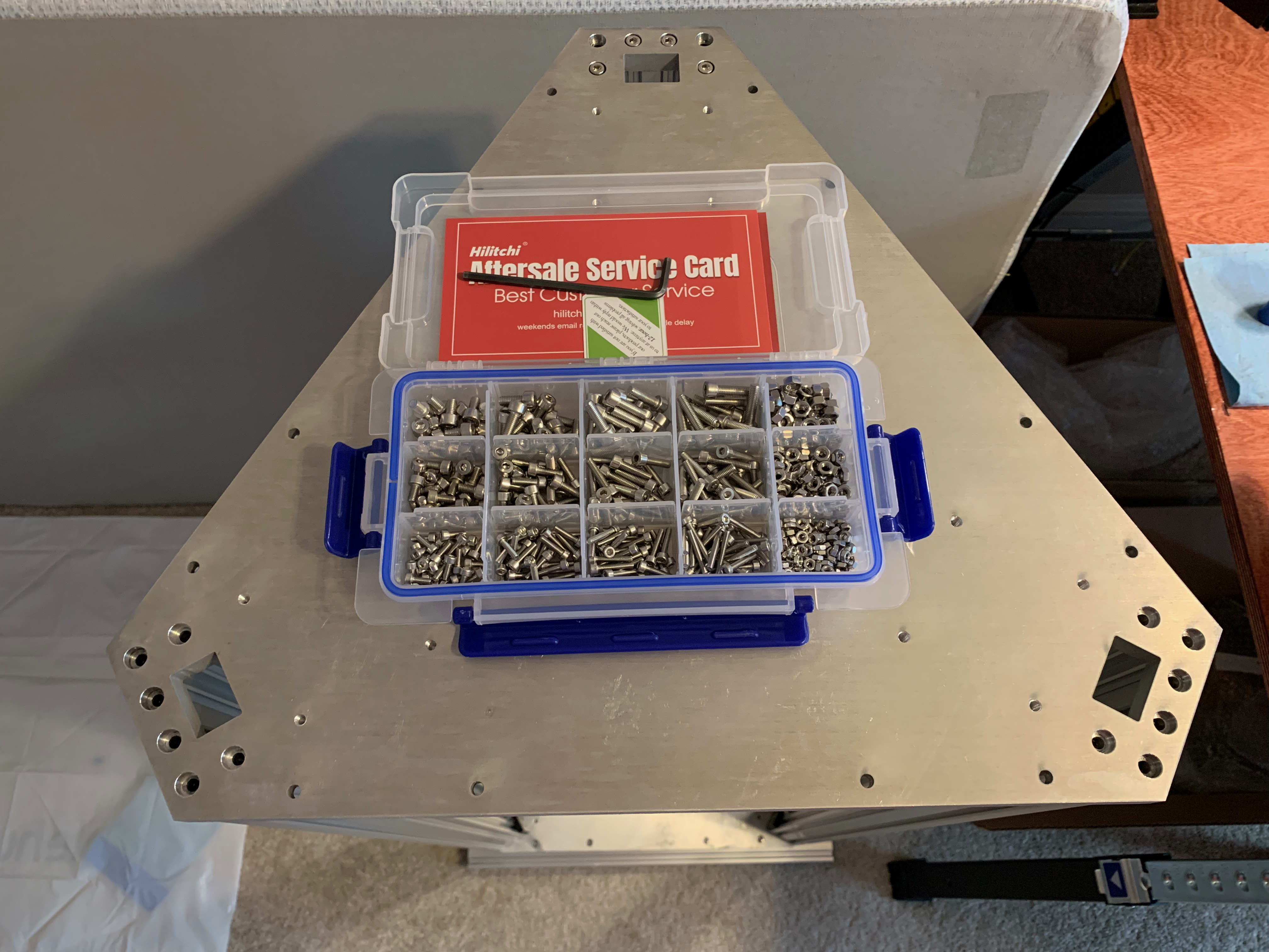
I got the frame plates waterjet cut out of 0.5" (12.7mm) 6061-T6 aluminum. The quoted material size is 32.0"x22.0" for both pieces. An alternative to that approach is to print the layout full scale, glue it to the uncut plate, then manually cut, center punch, and drill. That being said, the waterjet service was worth every penny. With some much-appreciated help from Al, we countersunk holes for socket cap screws using a mill/drill press.

My first iteration used standard plate for the bed plate and build plate. That's probably a facepalm moment for more experienced printer builders. Standard plate isn't flat enough for easy calibration or good first layers. And there are a limited number of mesh bed compensation points in firmware. Live and learn. So I'm using 0.375" cast aluminum tooling plate, again, waterjet cut. The part fits within a 16"x16" piece.
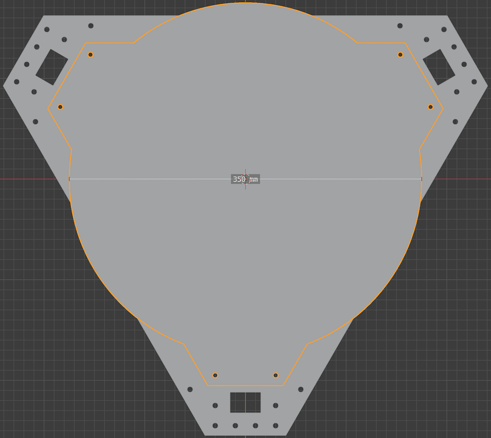
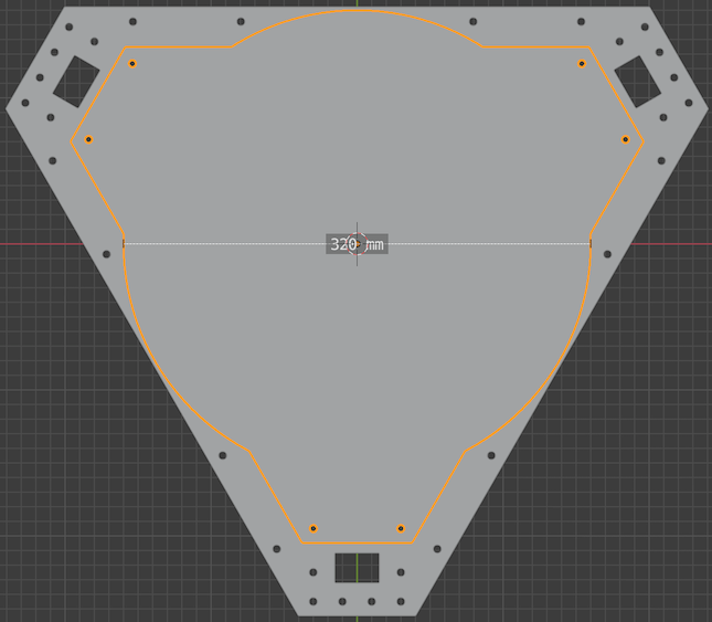
If you want the bed plate to fit within the frame plate footprint, adjust the circle to 320mm diameter. I opted for a 350mm circle, which extends beyond the frame plate, but still fits within the frame extrusion footprint.
The bed plate will mount on standoffs to threaded holes in the bottom frame plate. That same threaded hole location is used for part of the stepper motor mounts in the top frame plate.

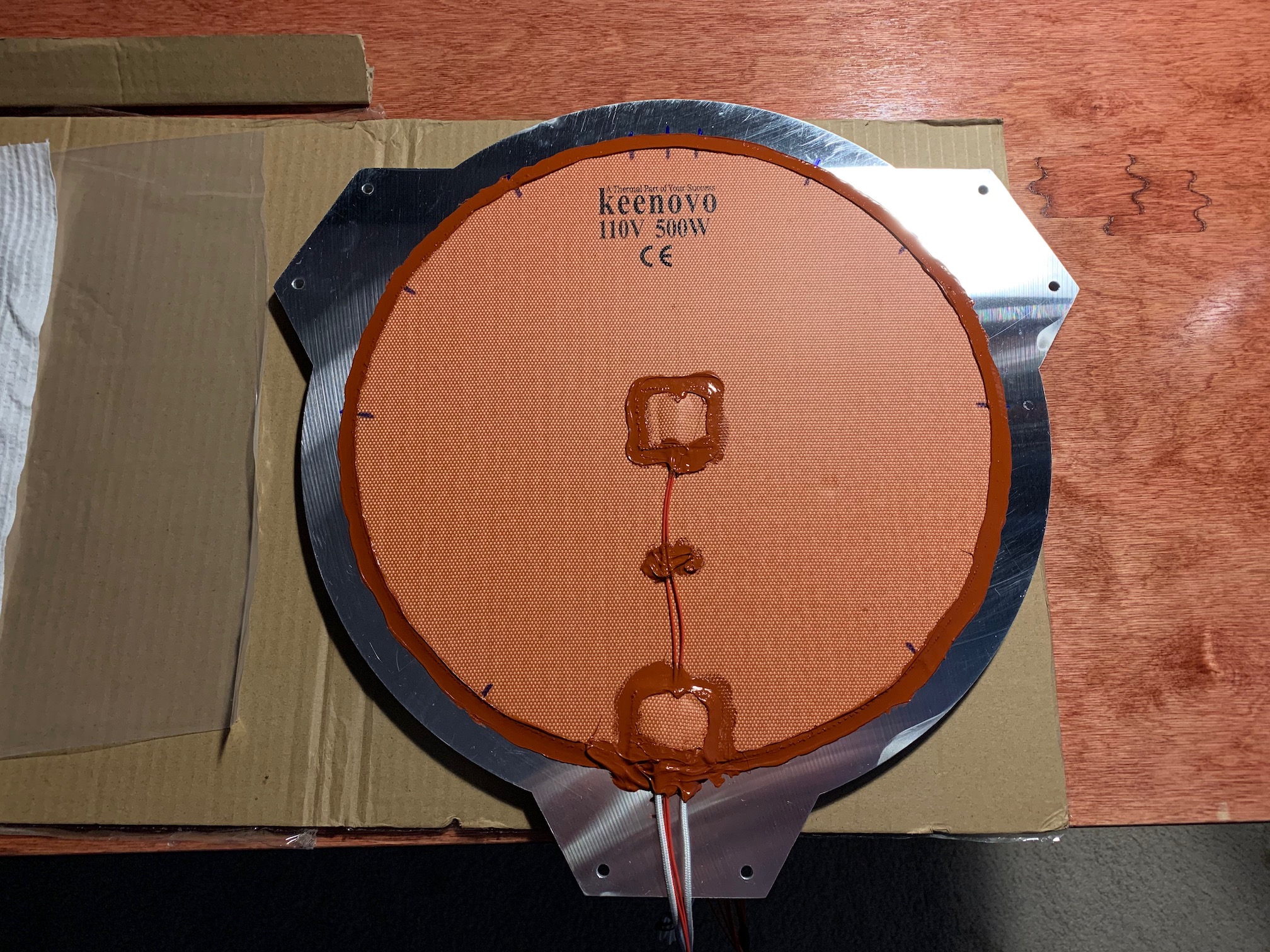
Again, don't use standard aluminum plate for this, unless you want headaches and crappy first layers. I thought about using magnetic flexible build surfaces like Wham Bam or BuildTak. But I thought I wouldn't be able to use the Delta Smart Effect nozzle probe while hot. Once you apply that magnetic base to a fixed bed, you're pretty committed, which limits options. On my Prusa's powder coated plate, low z offset made parts extremely hard to remove and that permanently discolored the sheet. A little higher was good for some parts and poor adhesion for others. I end up using glue stick for some prints anyway, so I though an aluminum or glass build surface would be ok. So I'm using 0.25" cast aluminum tooling plate. Two 350mm diameter build plates will fit on a 30"x15" piece. If printing on that turns out to be a headache, I'll try a stick-on surface on the removable plate or I'll try a glass plate.
Having two allows for different surfaces, preparing one plate while printing on another, etc.
I found Midwest Steel and Aluminum while searching for cast aluminum tool plate online. They offer circular bandsaw cuts of cast aluminum tool plate for a fraction of what waterjet parts would cost. They aren't as precise, but the material flatness and consistency are more important to me than diameter accuracy for this part. And if I get creative with a jig, I may be able to clean it up to a more accurate final diameter.

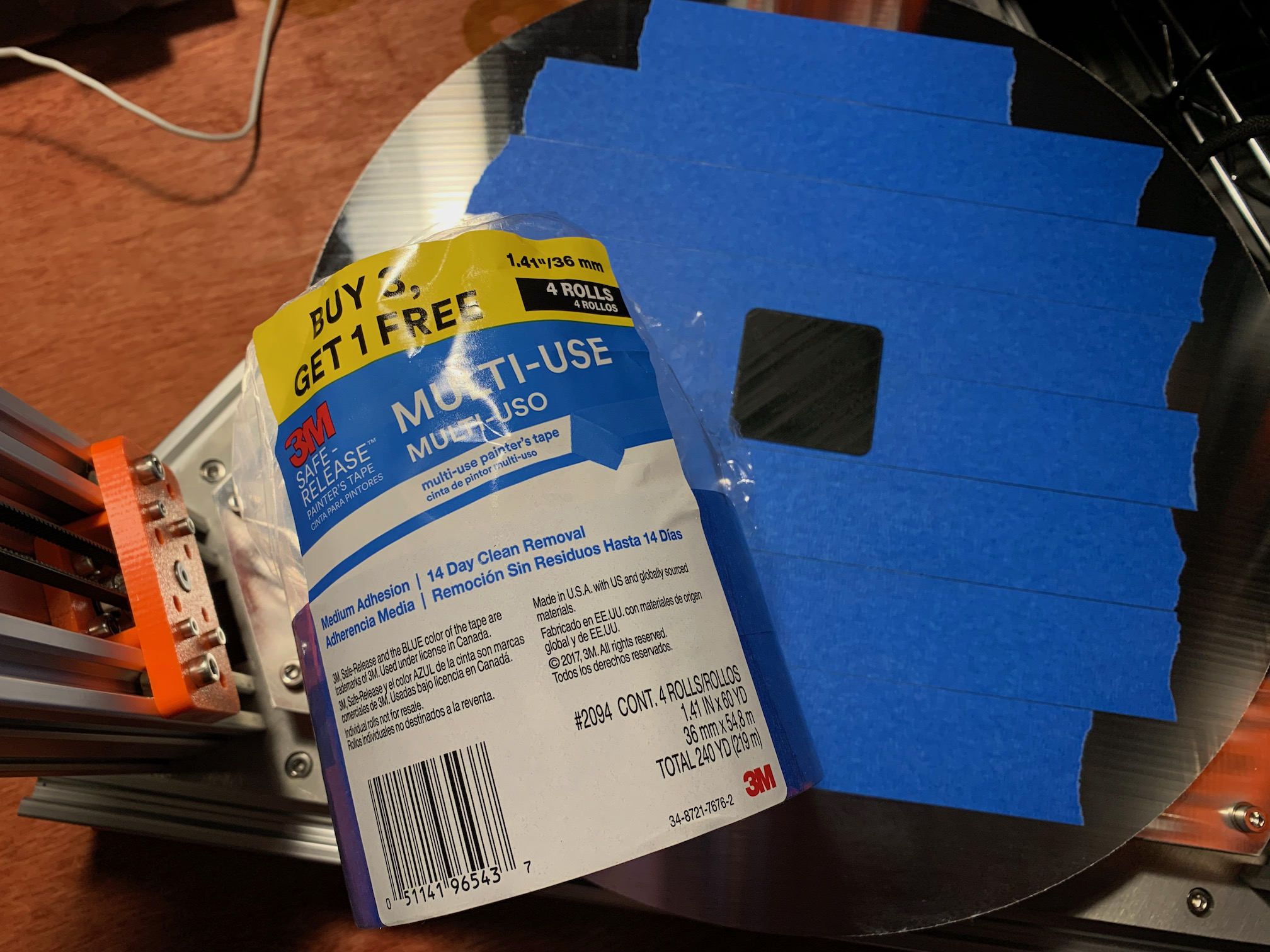
My initial layer testing with aluminum plus glue stick was hit and miss. As discussed in my videos, there were some issues that contributed to the hit and miss nature of my early first layer testing. But I was able to make significant progress after I switched to aluminum plus painters/masking tape for my build surface. The painters/masking tape has some give, which makes it more forgiving of first layer imperfections. I imagine this is why the rough texture of PEI powder coat build surfaces works well on the Prusa. If the nozzle is slightly too close, more plastic will flow into the valleys. The painters/masking tape also provides ridiculous adhesion for PLA and PETG, which I'm a big fan of. On the Prusa, I've had many prints ruined because they detached from the build plate or because the corners pulled up and warped the part. And I've had other parts that stuck way too well to the PEI powder coat. I'm not concerned with mass production, so I accept some build surface prep time in exchange for fewer failed prints. I've had good luck with 3M Multi-Use Painter's Tape. When it comes to removing well-bonded prints on a tape surface, I found two extremely helpful resources:
Overall, the DIY build plates with blue tape work very well. But large stiff prints can be very difficult to remove. Parts that don't flex mean prying tries to pull up on the whole surface area at once, which requires lots of force. Smaller, thinner, more flexible parts peel away from the tape and are easier to remove, less force. Prying up parts with a razor and scraper can definitely scratch and gouge the aluminum. Dressing the surface with a stone helps, but the damage adds up over time. Maybe that's ok given the relatively low cost of the cast aluminum build plates.
After refining enough to get nice prints and doing a bunch of functional prints, I switched to the Wham Bam Flexible Build System (PEX). The primary reason was for easier print removal. A side benefit is faster heat up time.
I deburred holes in the frame plates and holes in the ends of the c-beams. I also went over the mating surfaces of the c-beams and the frame plates with a flat stone. I used blue/medium threadlocker on the bottom plate to c-beam fasteners. I used anti-seize on the top plate to c-beam fasteners. I drilled and tapped all of the 4mm holes in the frame plates.
After securing the bottom plate and 1/3 of the top plate, I noticed about 1/2 hole out of alignment on the remaining two c-beams. Between that and checking things with a square, I was pretty happy with the factory end squareness on the c-beams. For now, I'm opting to not mill or grind the ends of the c-beams. If test prints prove inaccurate, I may revisit that.
You can print these parts or have them printed for you. I still have my first 3D printer while I'm building this printer, so I'm printing them myself. There are definitely other ways to make these parts, but I'm using the tools available to me. I printed the prototype parts in PLA or PETG with thin walls and low infill. For the most part, I printed the functional parts in PETG with 100% infill. If there are any shortcomings due to flex, heat, etc., I may reprint in another material. But I don't have any experience with ABS, ASA, Nylon, or PC yet.
I designed most of the parts for this project, but I sourced a few part designs from elsewhere as noted in the Source column of the table. I designed these parts in Blender because I like using it and I'm a big fan of open source. Maker Tales has a bunch of helpful YouTube videos for this sort of thing. Two of my favorite playlists are Intro to Blender 2.8 and Precision Modeling and Learn Blender 2.9+ Through Precision Modeling.
| Part | Screenshot | Photo | Source | STL | Quantity | Status, Notes |
|---|---|---|---|---|---|---|
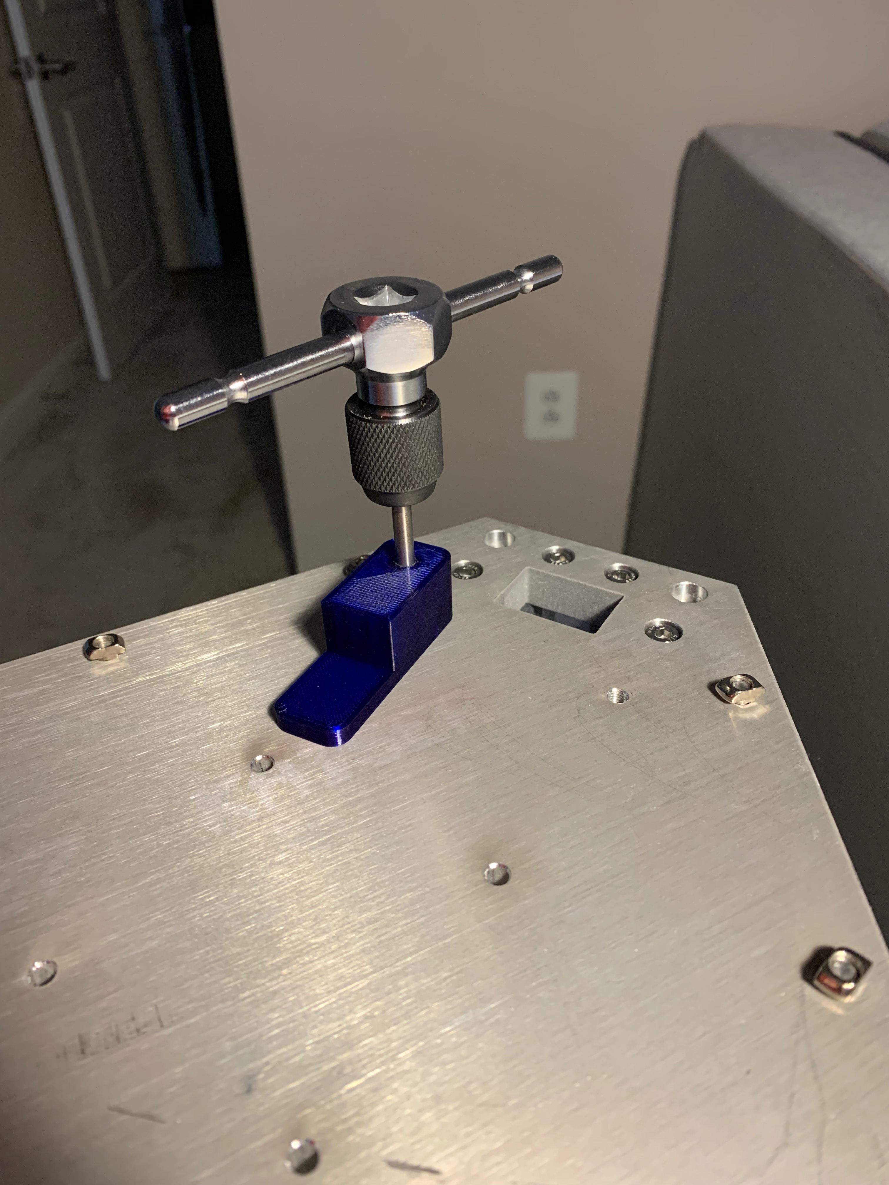
| M5 tap guide | 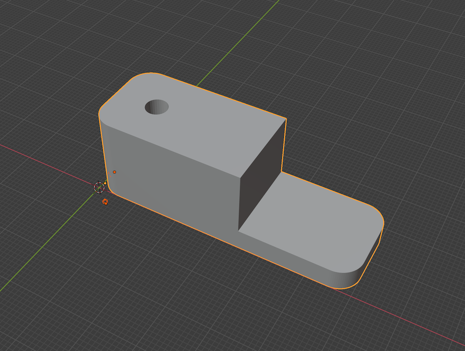 |
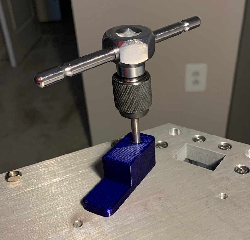 |
tap_guide.blend | tap_guide.stl | 1 | printed |
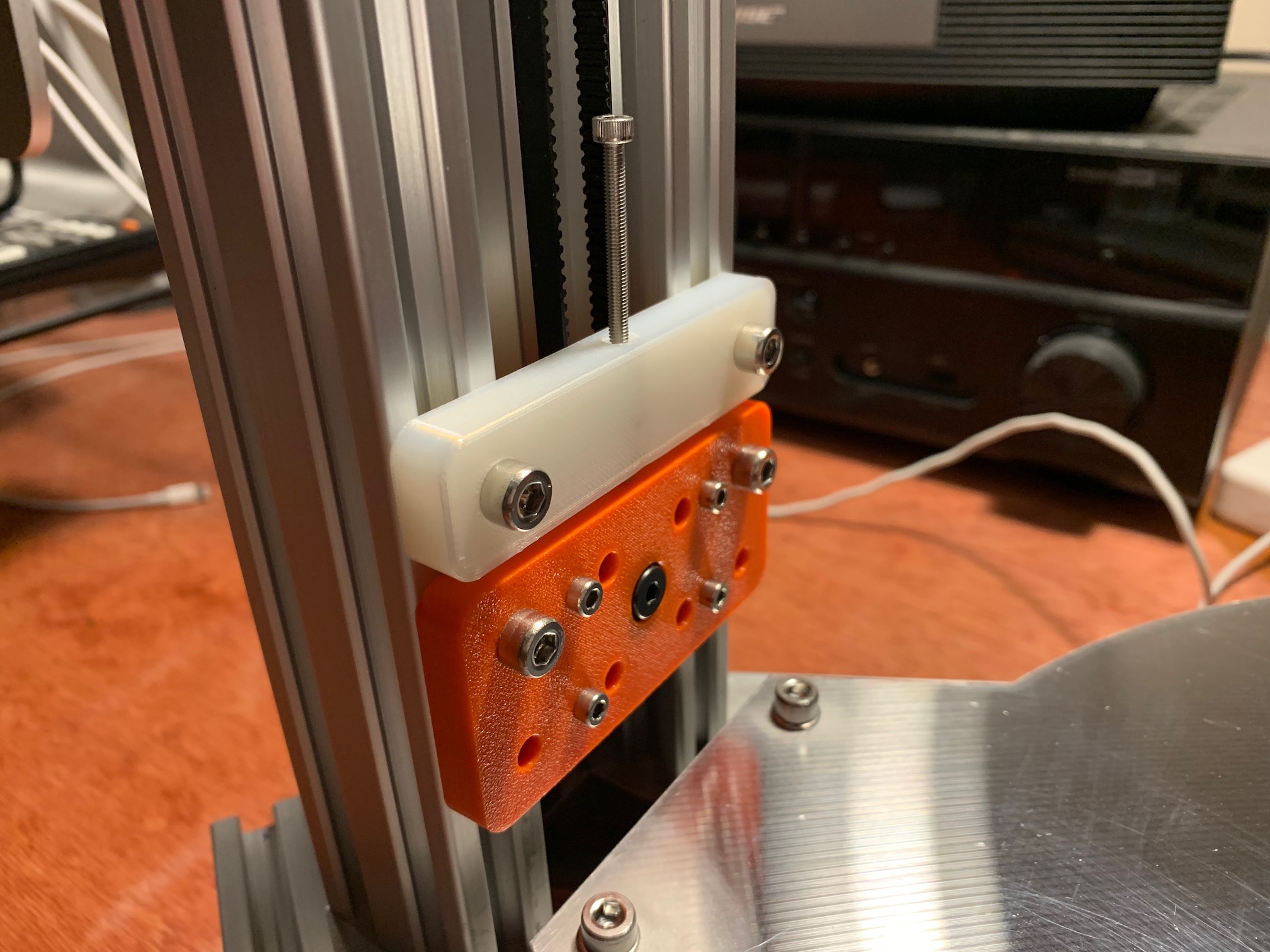
| stepper motor mount | 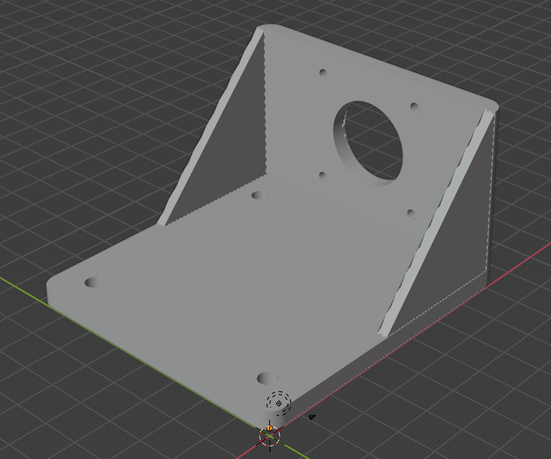 |
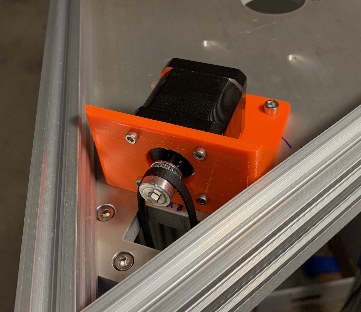 |
stepper_mount.blend | stepper_mount.stl | 3 | printed |
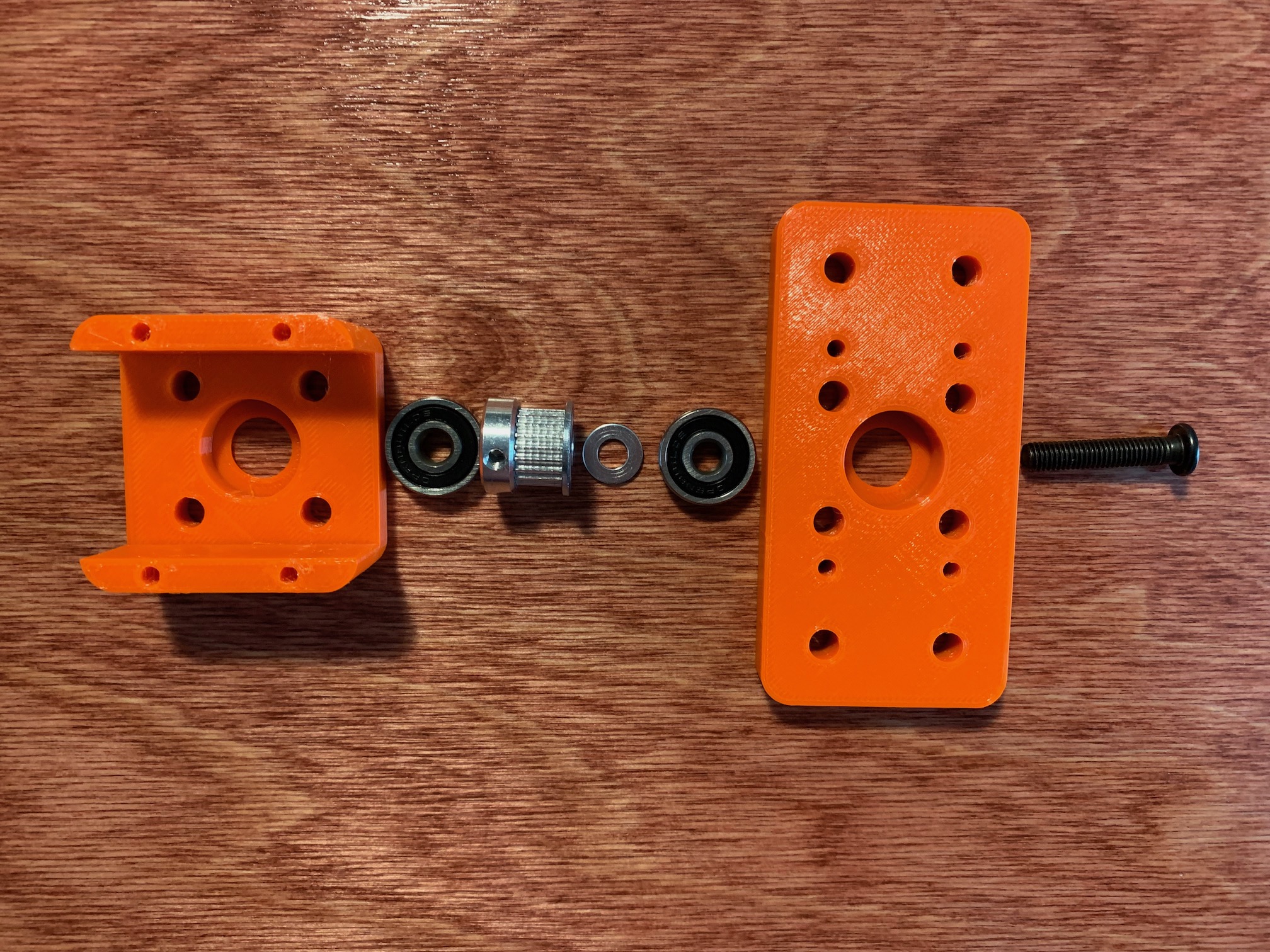
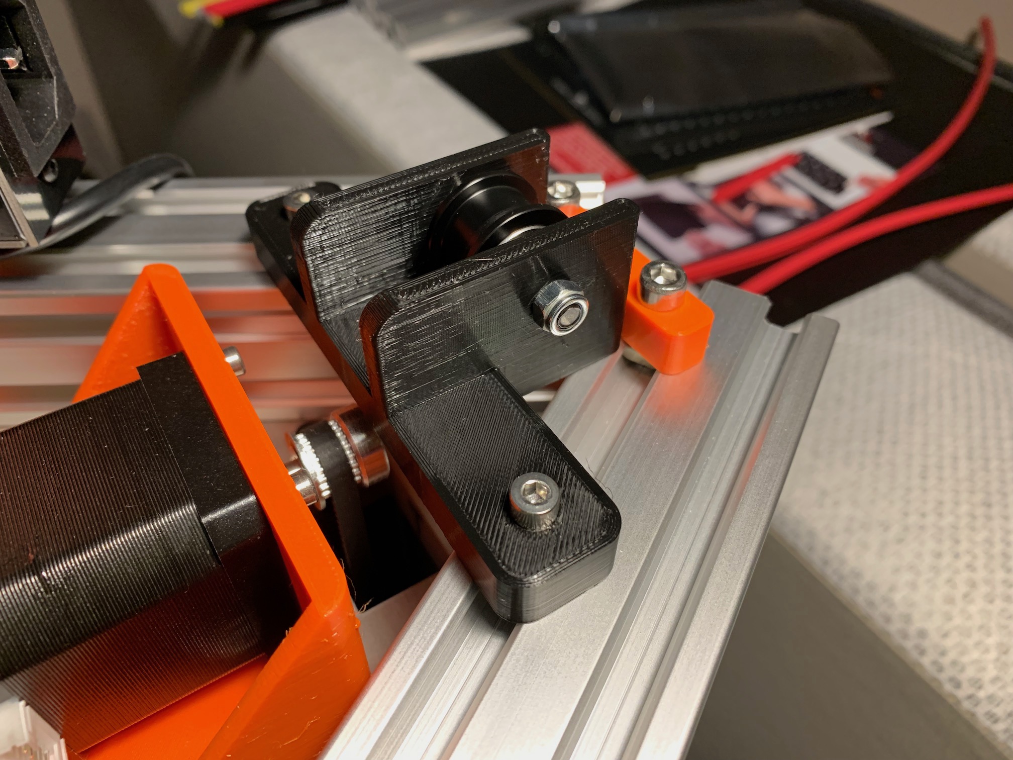
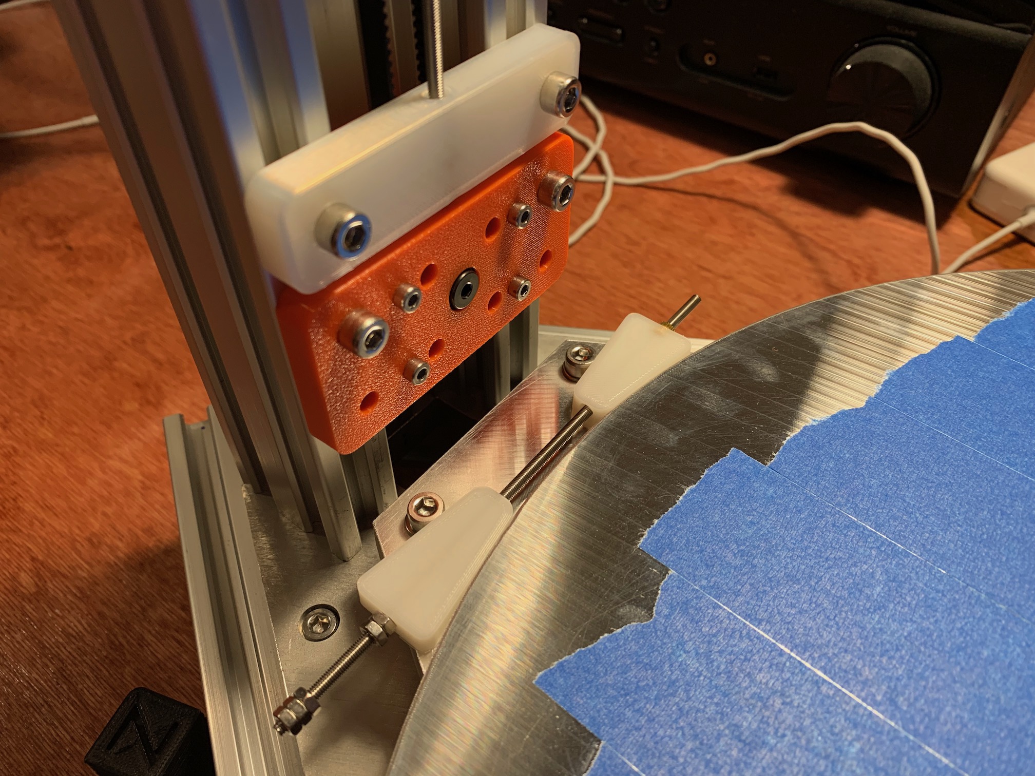
| stepper motor mount r2 | 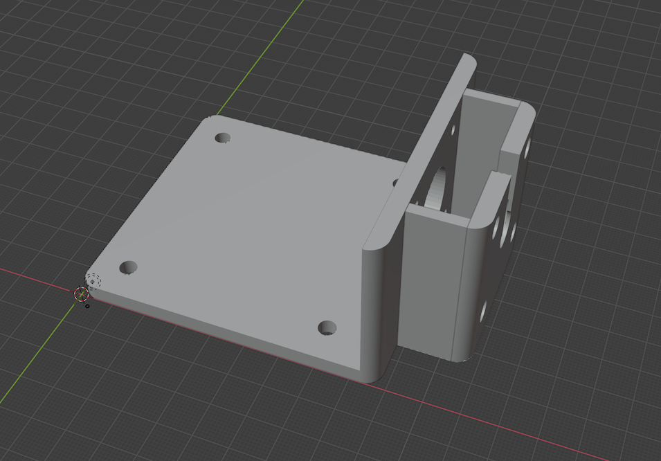 |
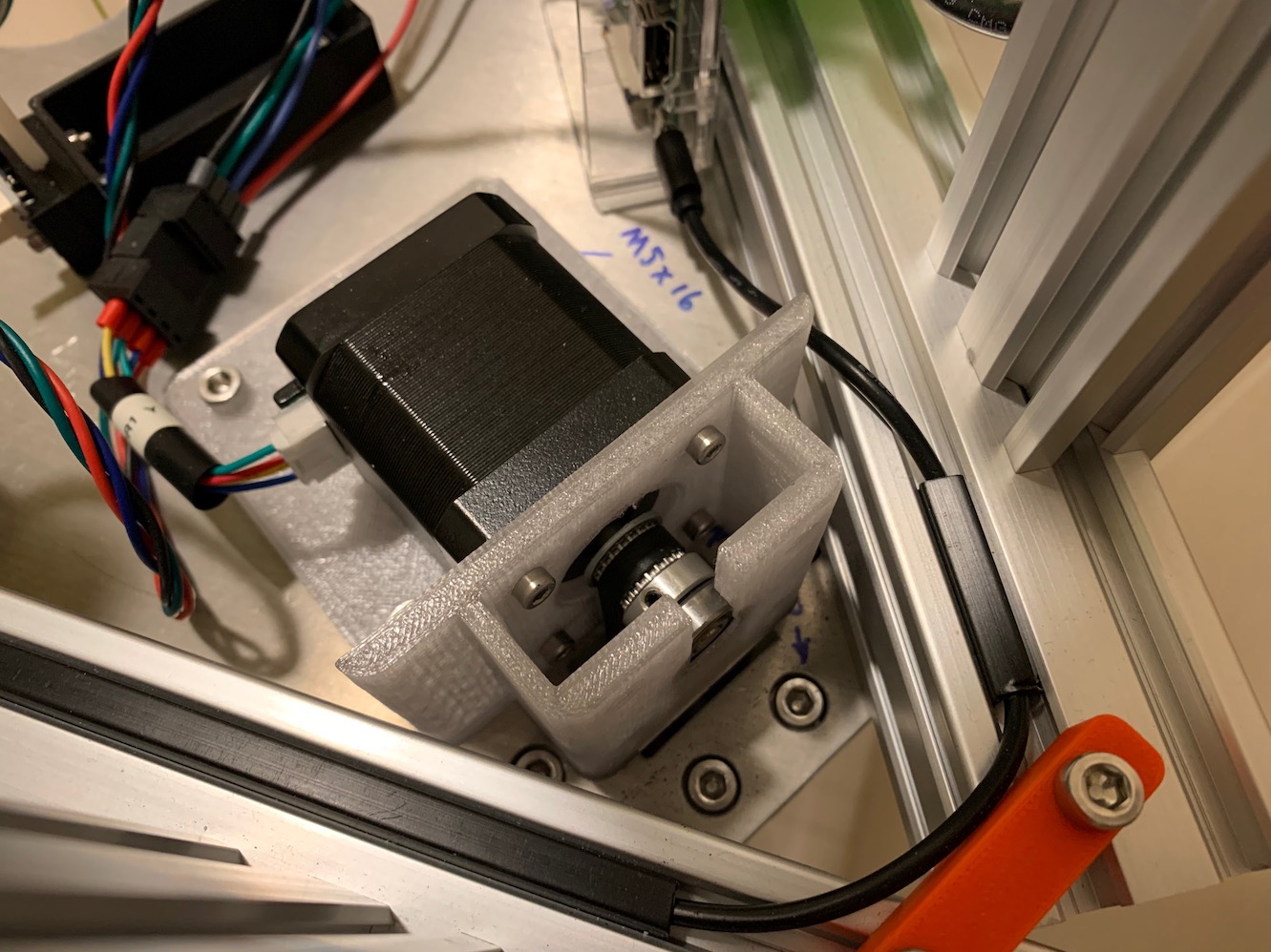 |
stepper_mount_r2.blend | stepper_mount_r2.stl | 3 | printed, shaft end bearing for better squareness and more belt tension |
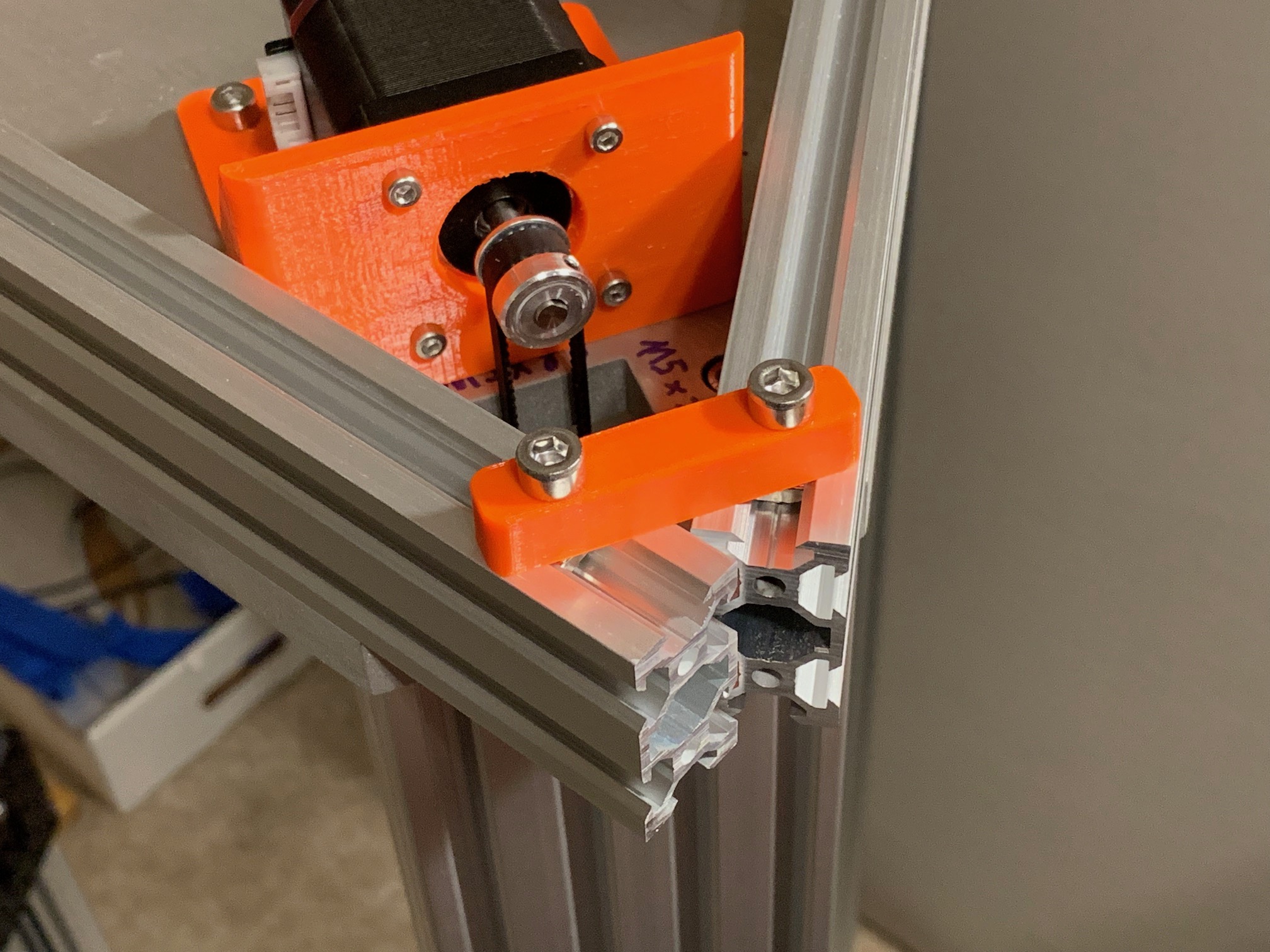
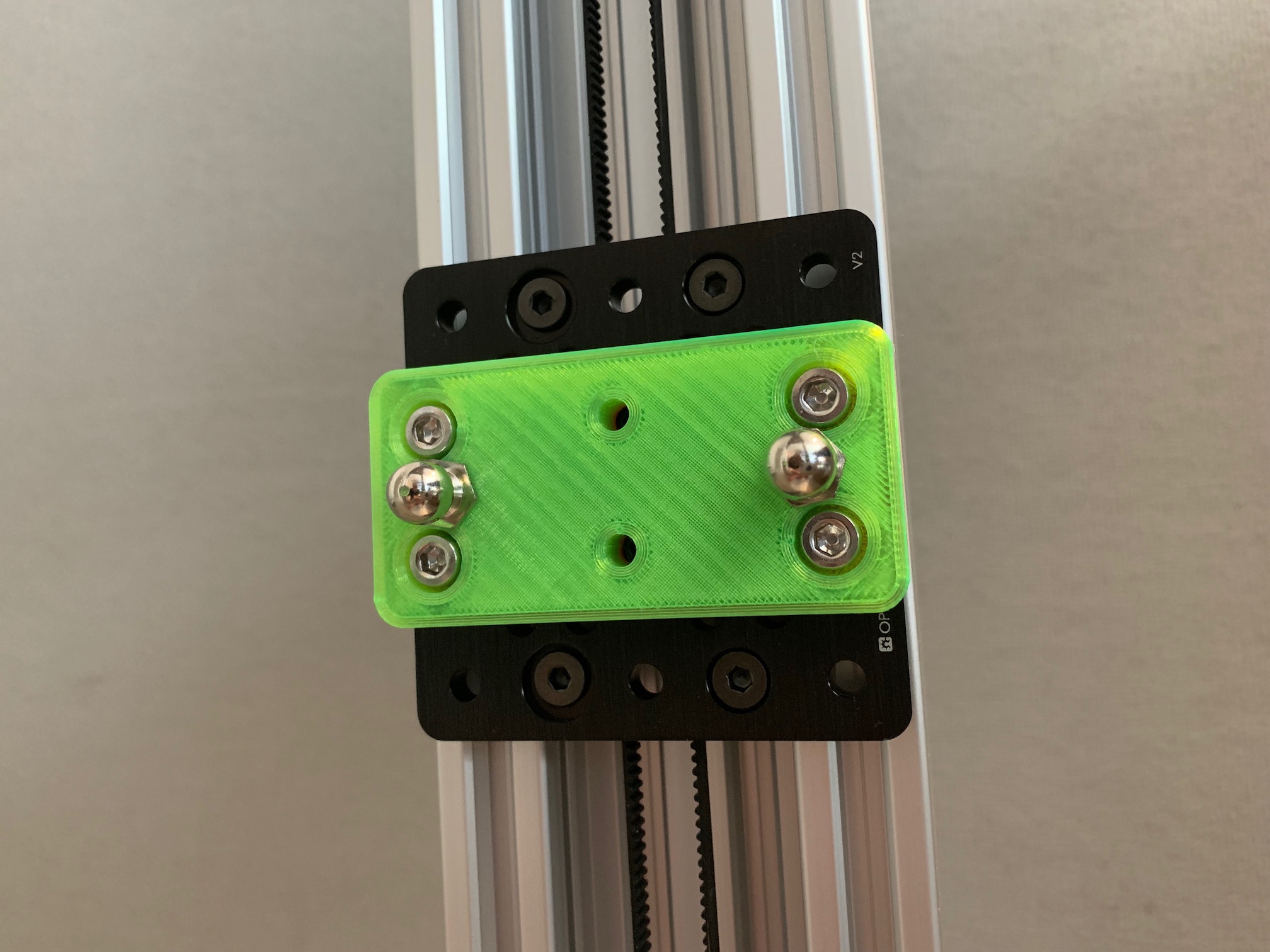
| timing belt clamp | 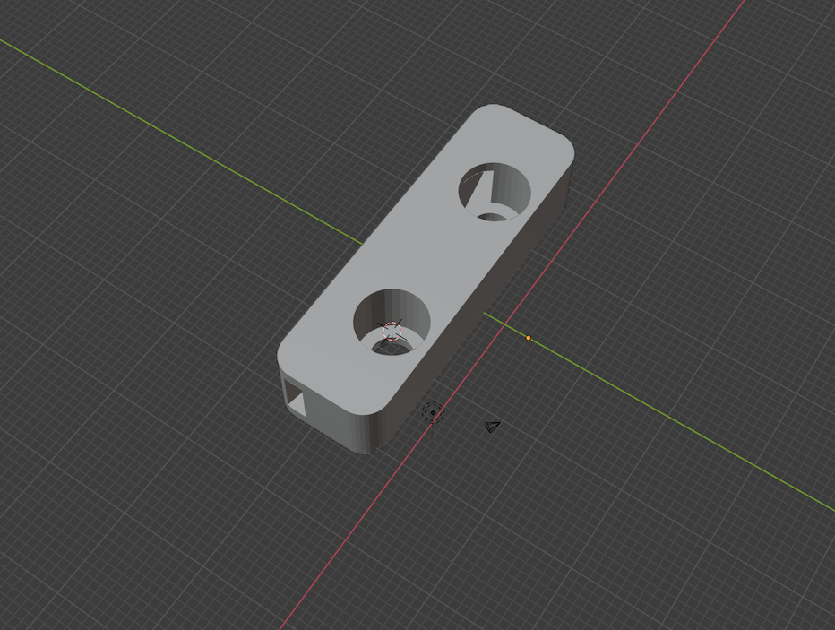 |
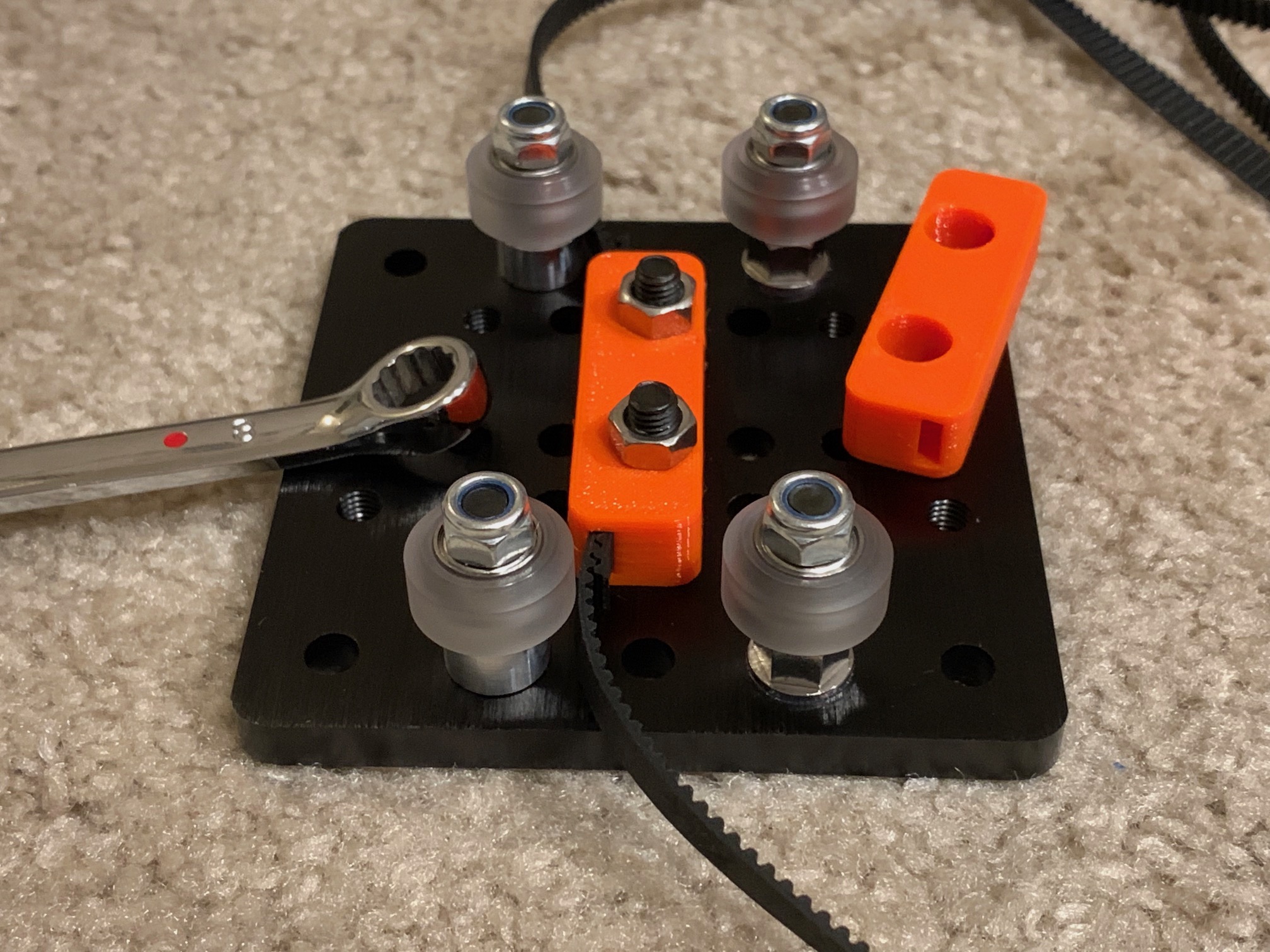 |
belt_clamp.blend | belt_clamp.stl | 3 | printed, for OpenBuilds 5mm belt |
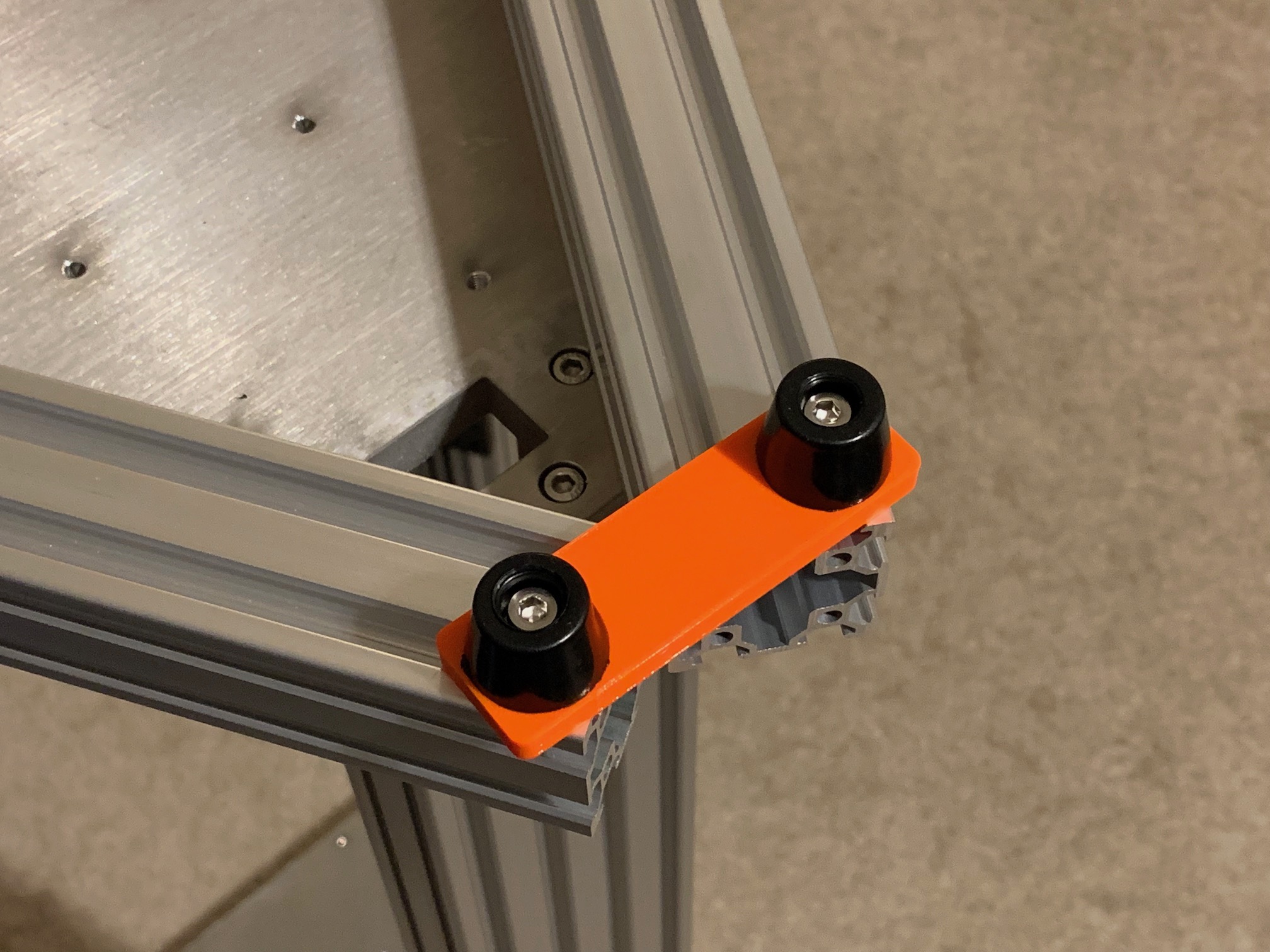
| timing belt clamp r2 | 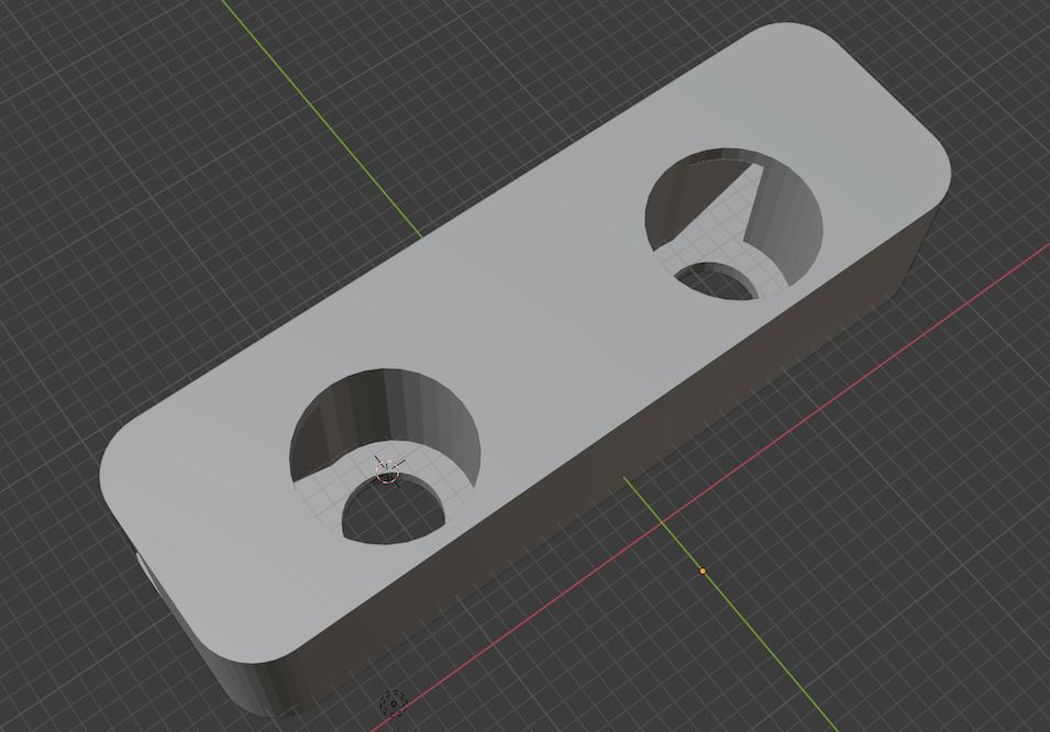 |
 |
belt_clamp_r2.blend | belt_clamp_r2.stl | 3 | printed, for Gates 6mm belt |
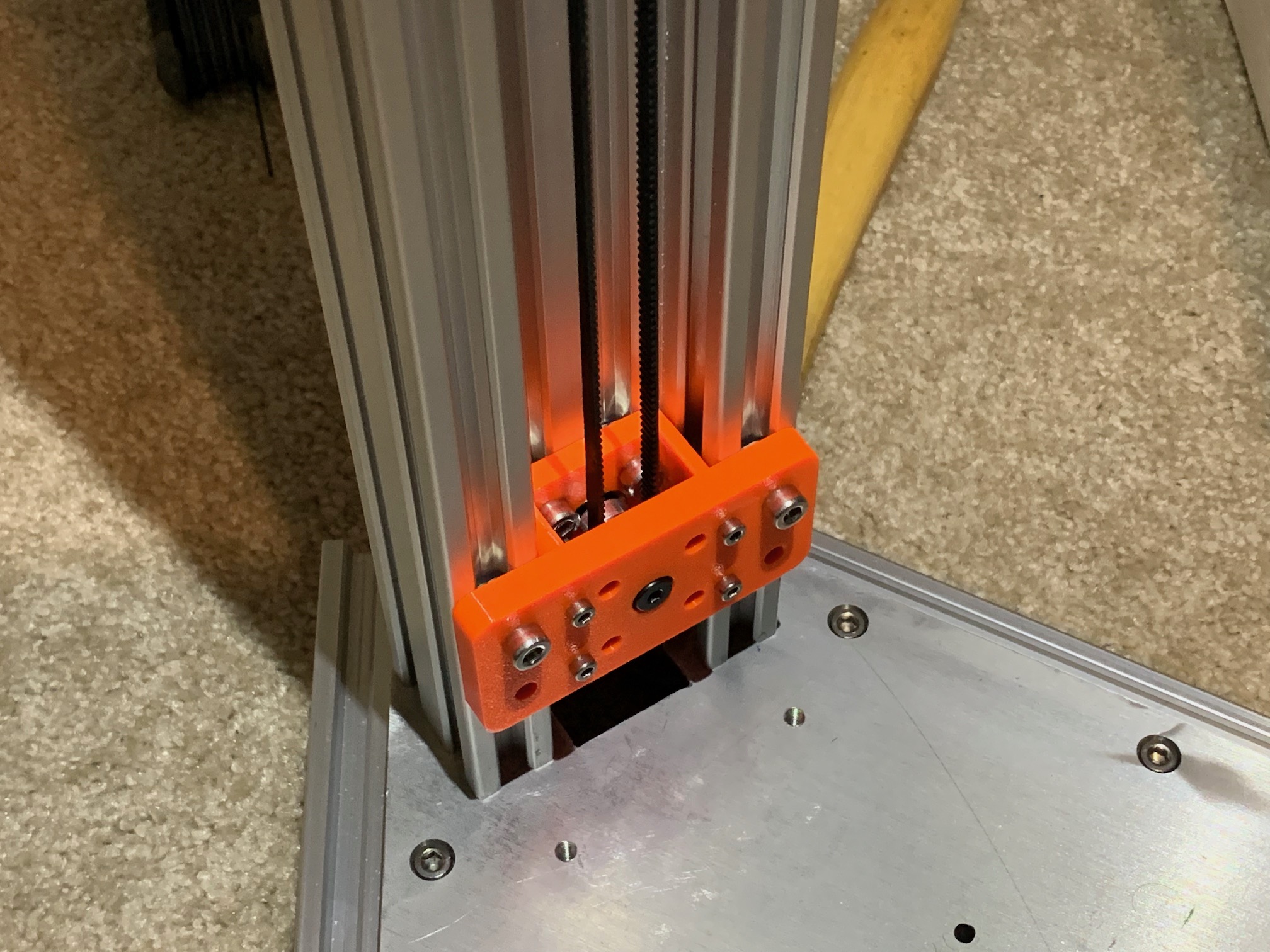
| idler plate front |  |
 |
idler_plate_front.blend | idler_plate_front.stl | 3 | printed |
| idler plate back | 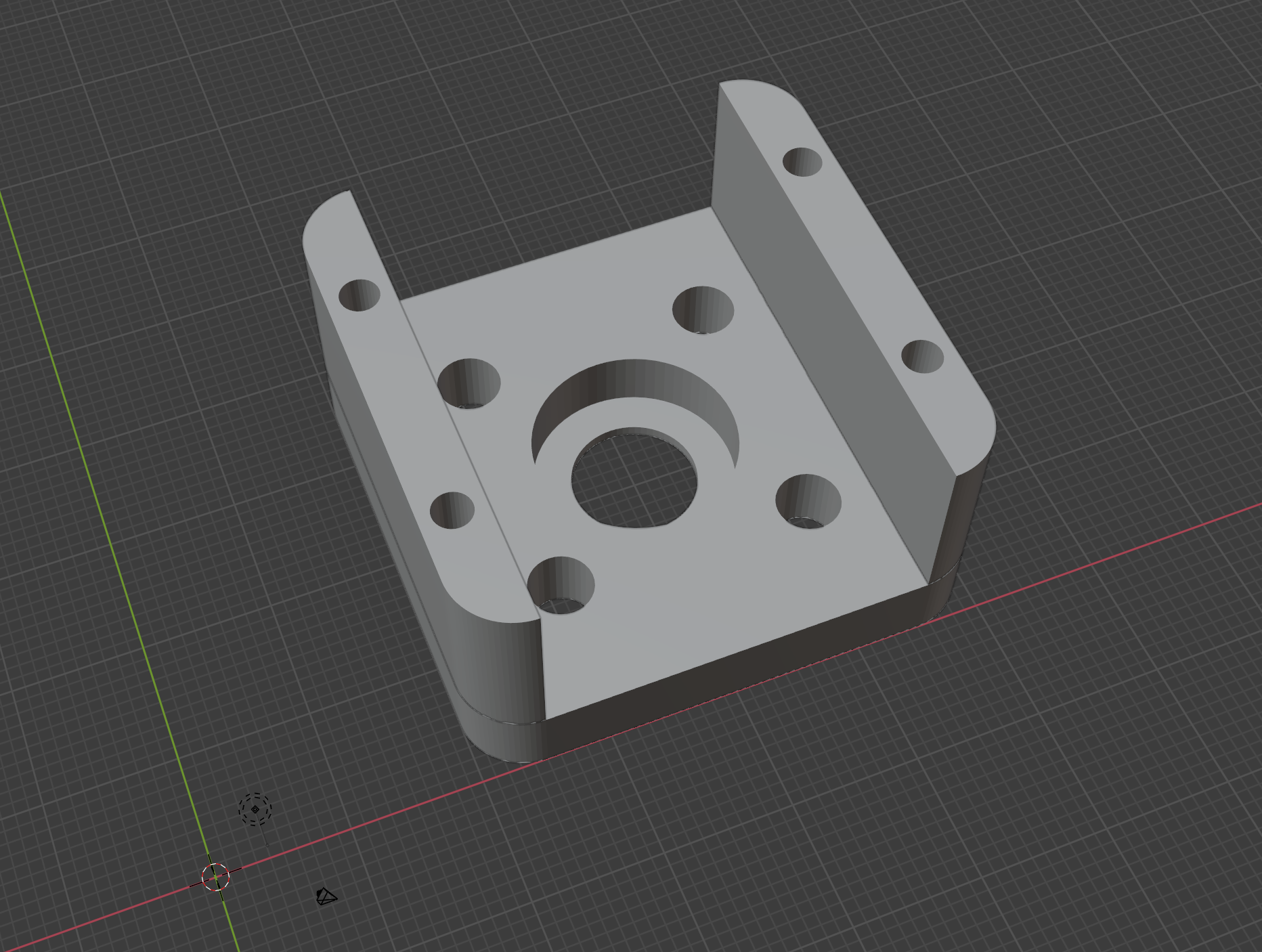 |
 |
idler_plate_back.blend | idler_plate_back.stl | 3 | printed |
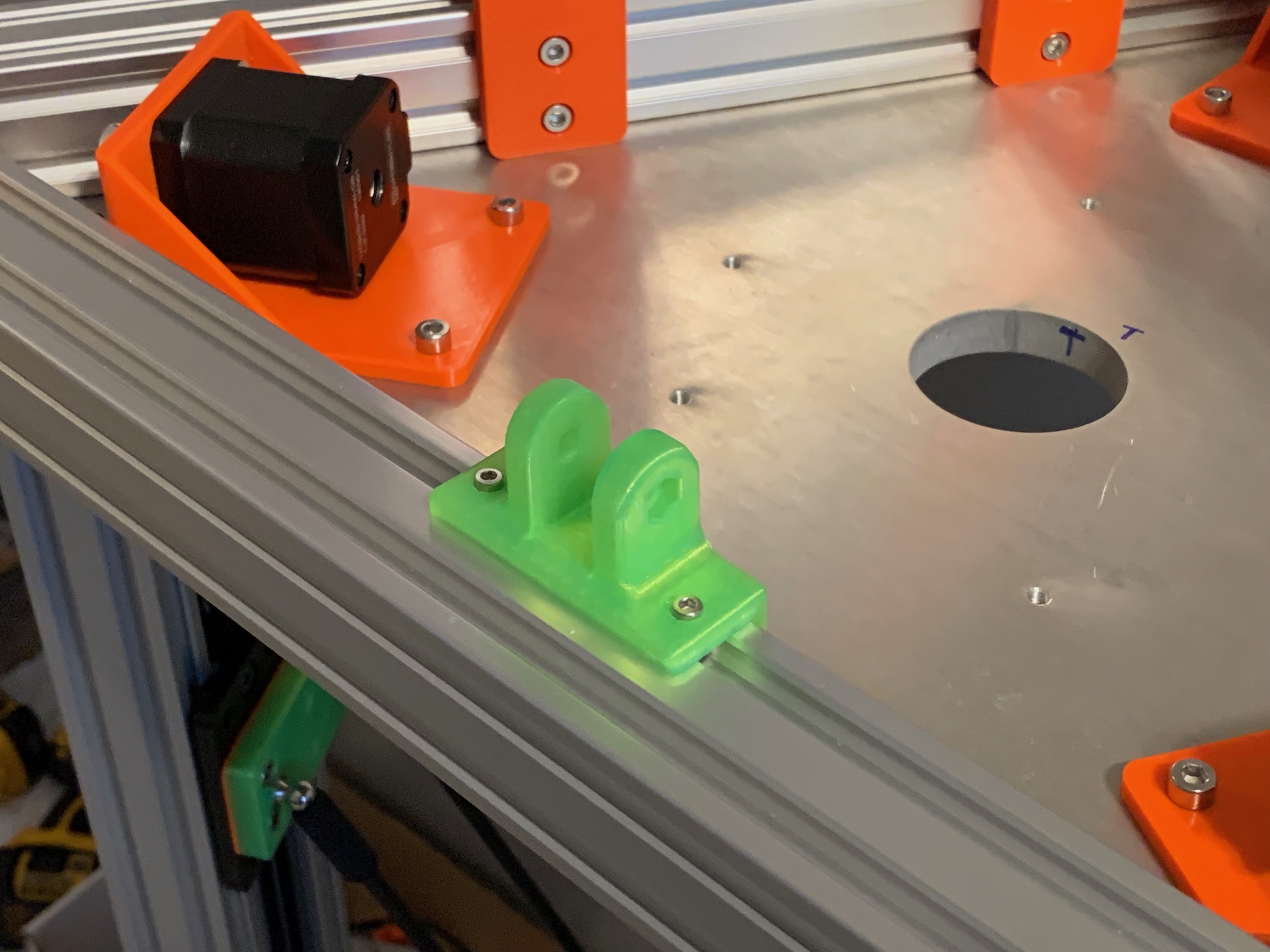
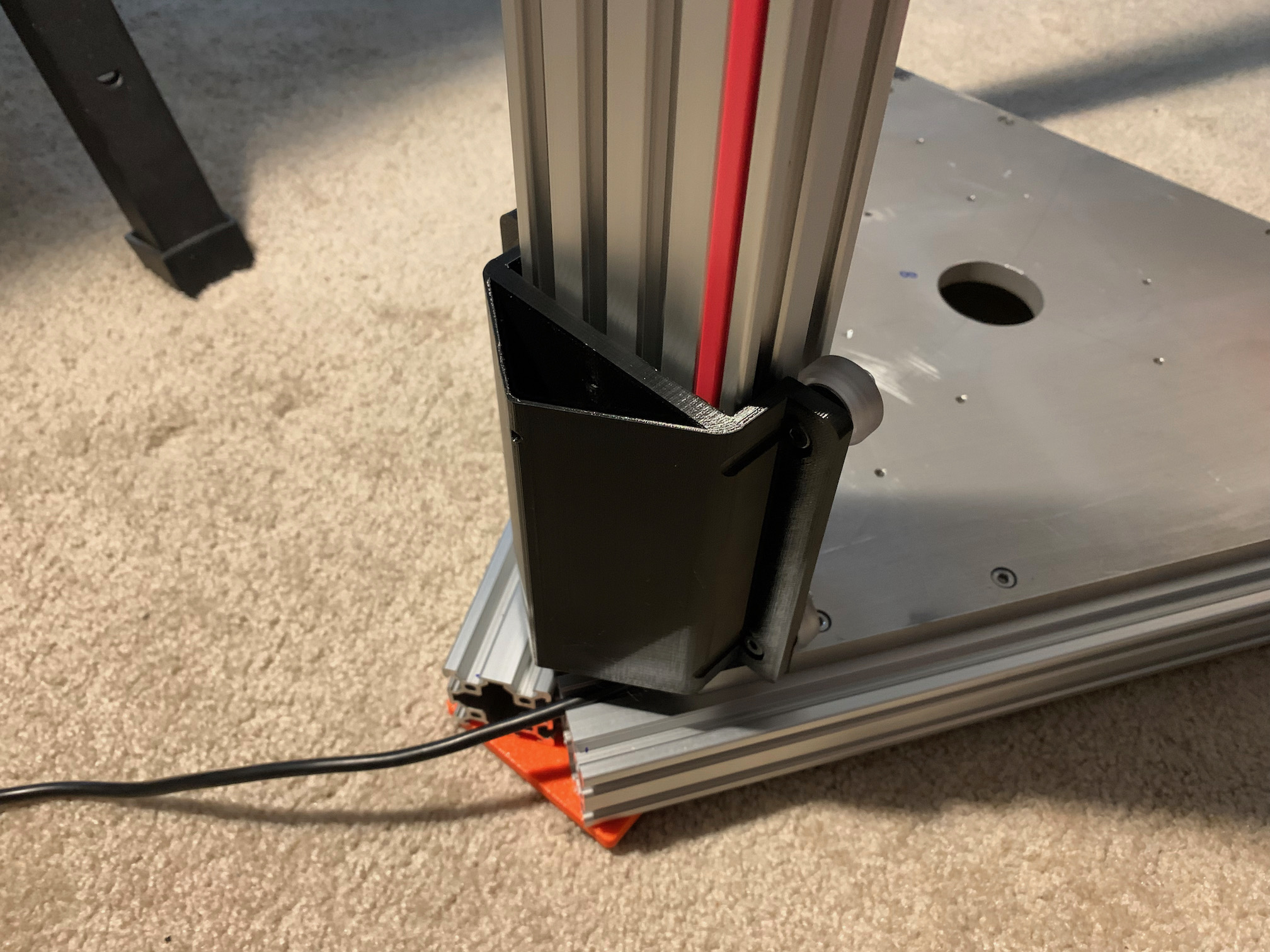
| extrusion brace | 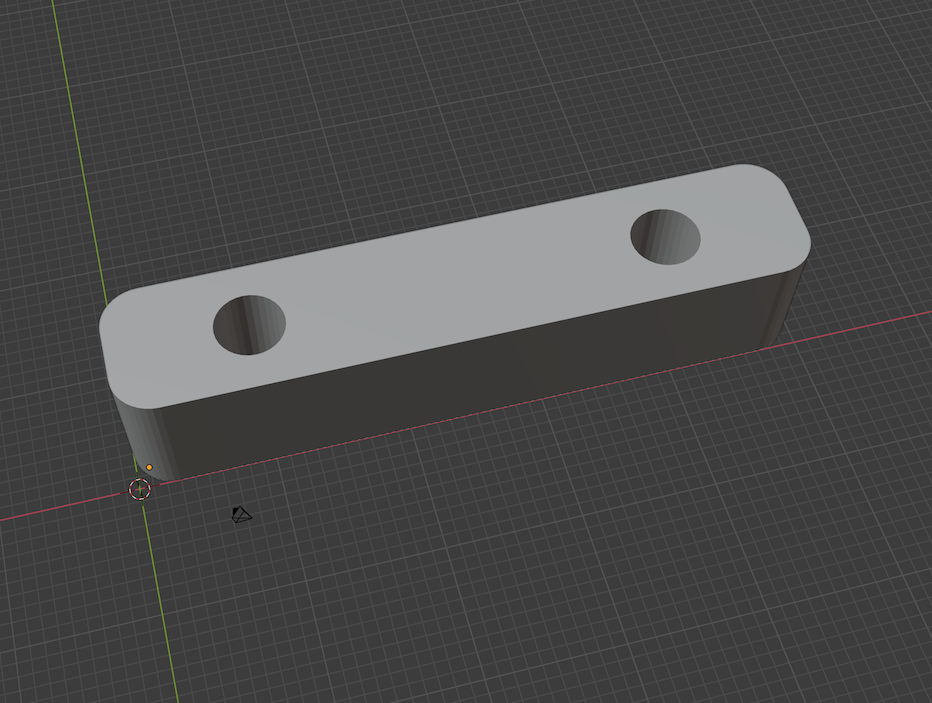 |
 |
extrusion_brace.blend | extrusion_brace.stl | 3 | printed |
| foot brace | 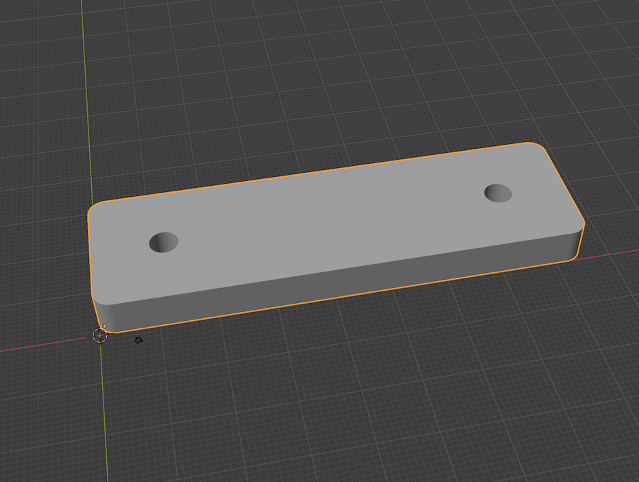 |
 |
foot_brace.blend | foot_brace.stl | 3 | printed |
| gantry magball mount | 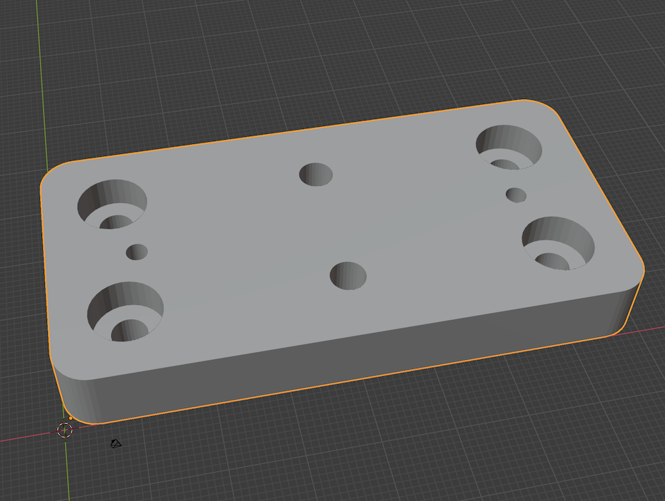 |
 |
gantry_magball_mount.blend | gantry_magball_mount.stl | 3 | printed, 330mm build diameter w/ mount, 350mm build diameter w/ drilled/tapped gantry plate, takes t-nut in rear |
| power supply bracket | 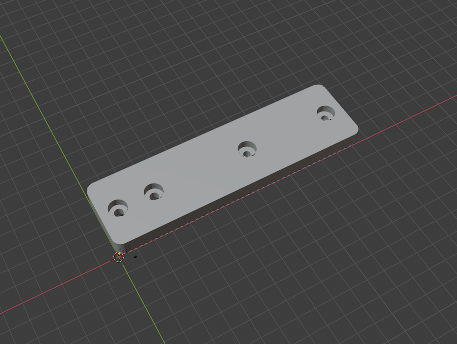 |
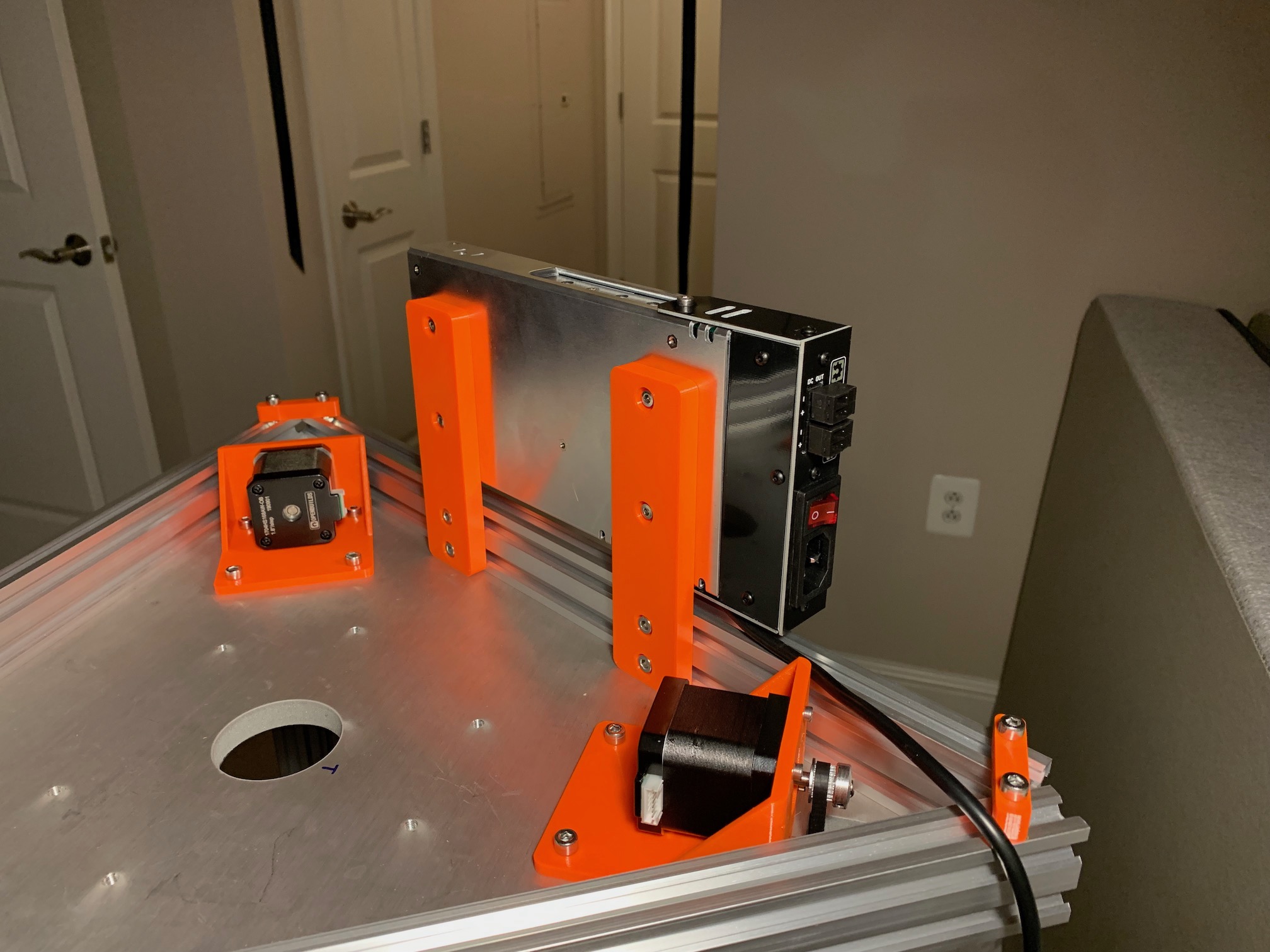 |
ps_bracket.blend | ps_bracket.stl | 2 | printed |
| Duet 3 mainboard box | 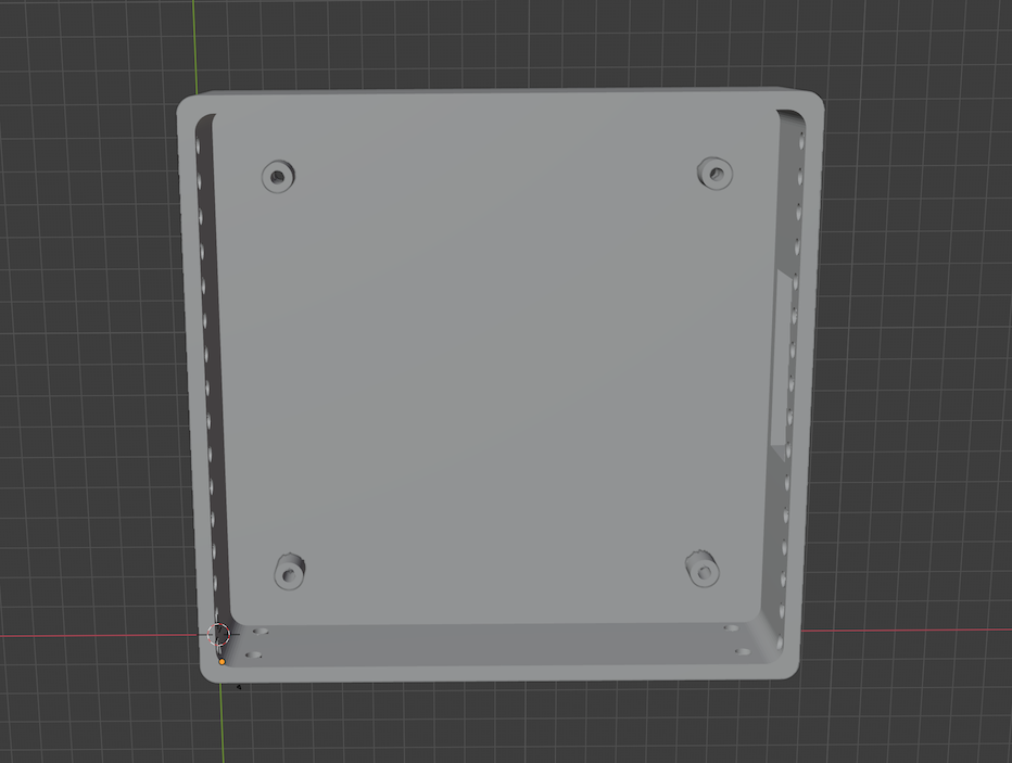 |
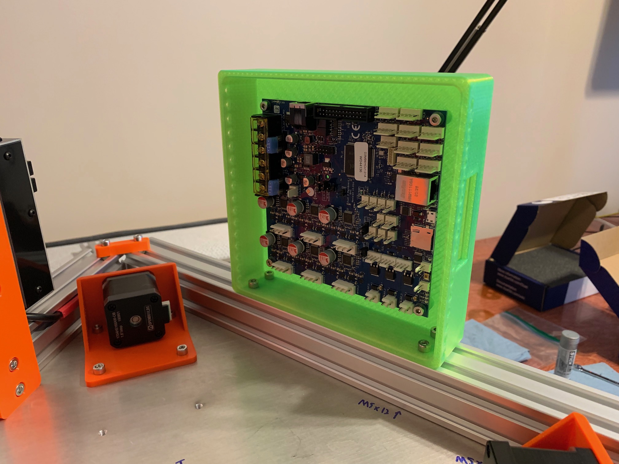 |
duet3_box.blend | duet3_box.stl | 1 | printed |
| PanelDue 7i case front | 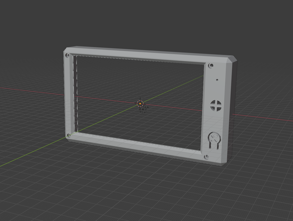 |
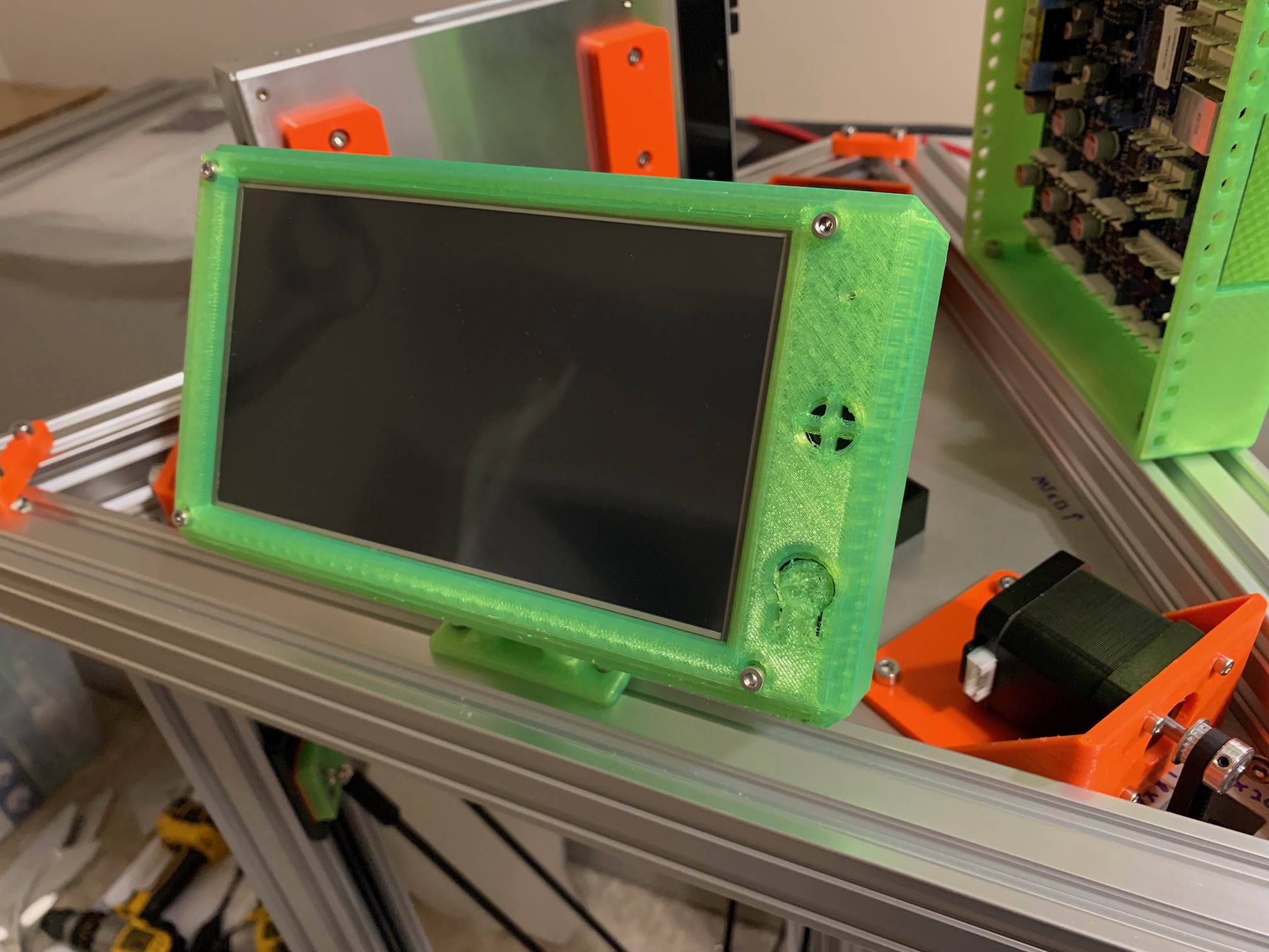 |
Thingiverse LumberjackEngineering CC | 7i_Case_Front.stl | 1 | printed |
| PanelDue 7i case rear | 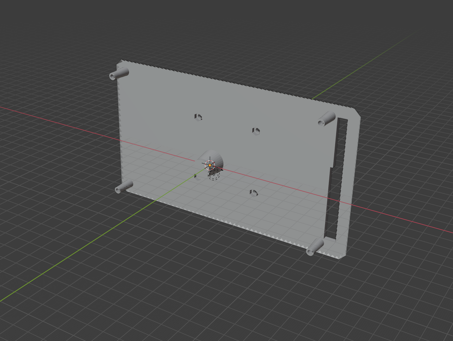 |
 |
Thingiverse LumberjackEngineering CC | 7i_Case_Rear.stl | 1 | printed |
| PanelDue 7i mount display | 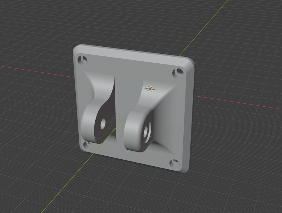 |
|
Thingiverse LumberjackEngineering CC | 7i_Mount_Display.stl | 1 | printed |
| PanelDue 7i mount arm | 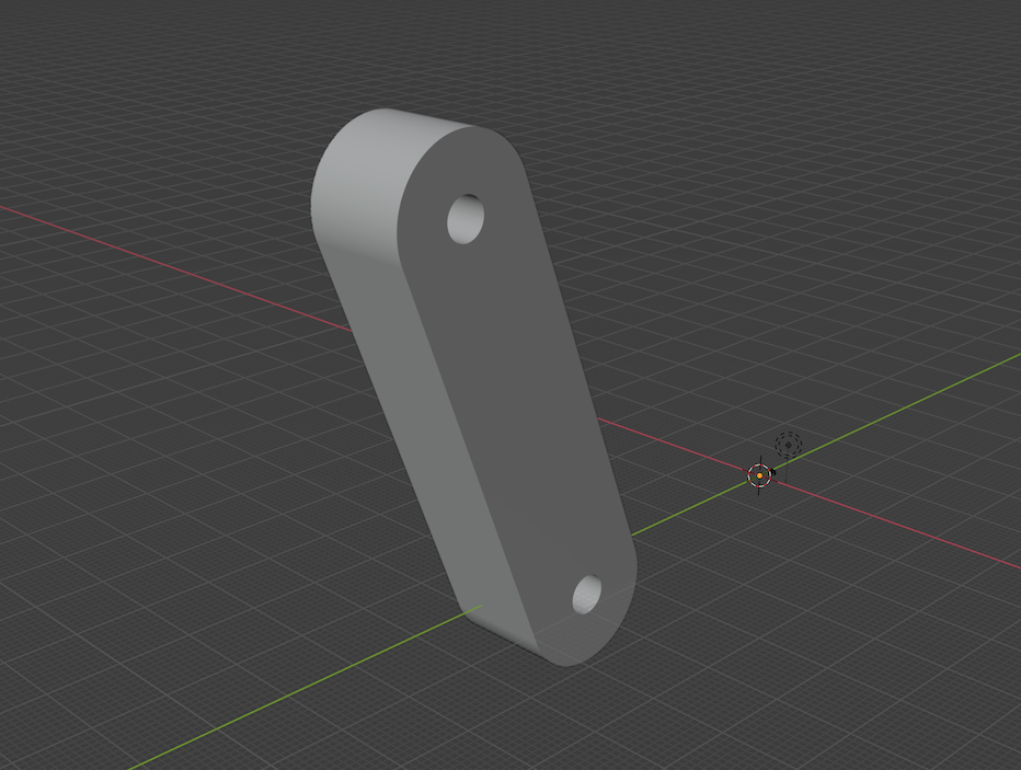 |
|
Thingiverse LumberjackEngineering CC | 7i_Mount_Arm.stl | 1 | printed |
| PanelDue 7i mount frame | 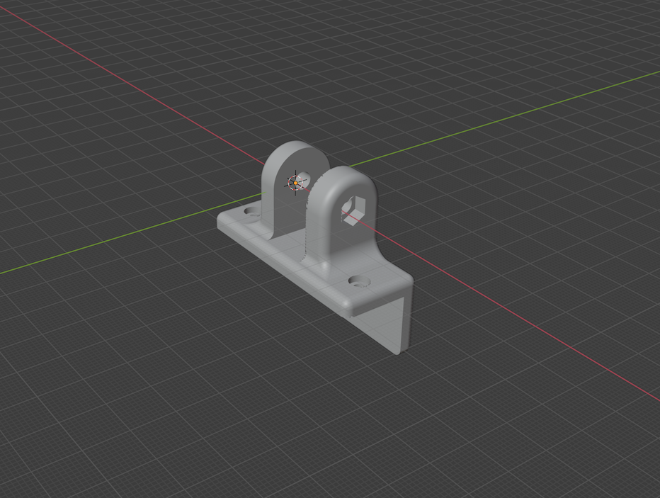 |
 |
Thingiverse LumberjackEngineering CC | 7i_Mount_Frame_2020.stl | 1 | printed |
| counterweight gantry | 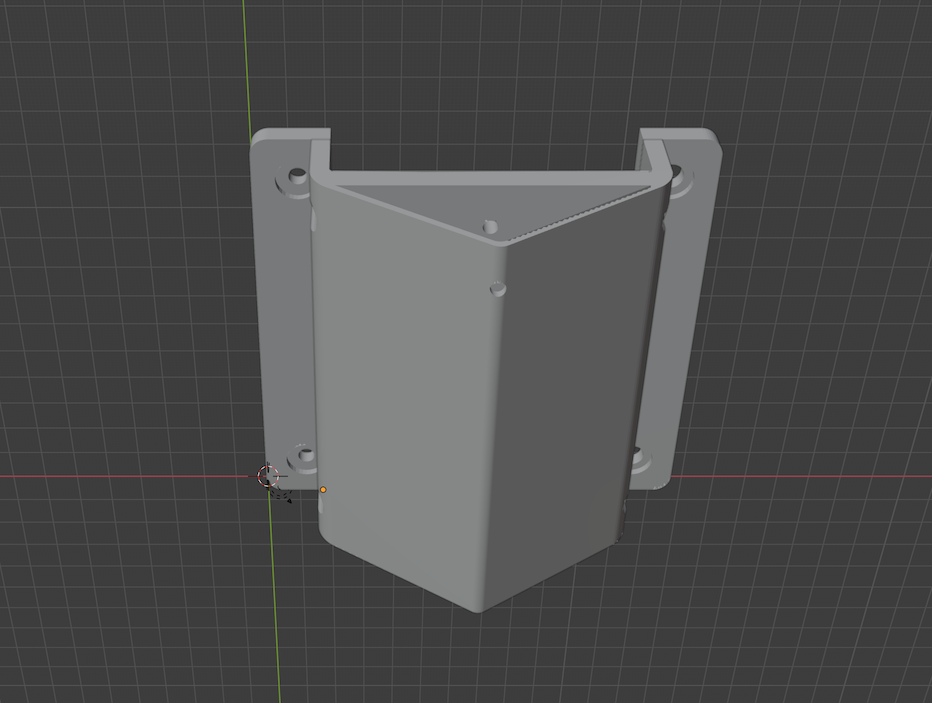 |
 |
counterweight_gantry.blend | counterweight_gantry.stl | 1 | printed |
| counterweight idler 1 | 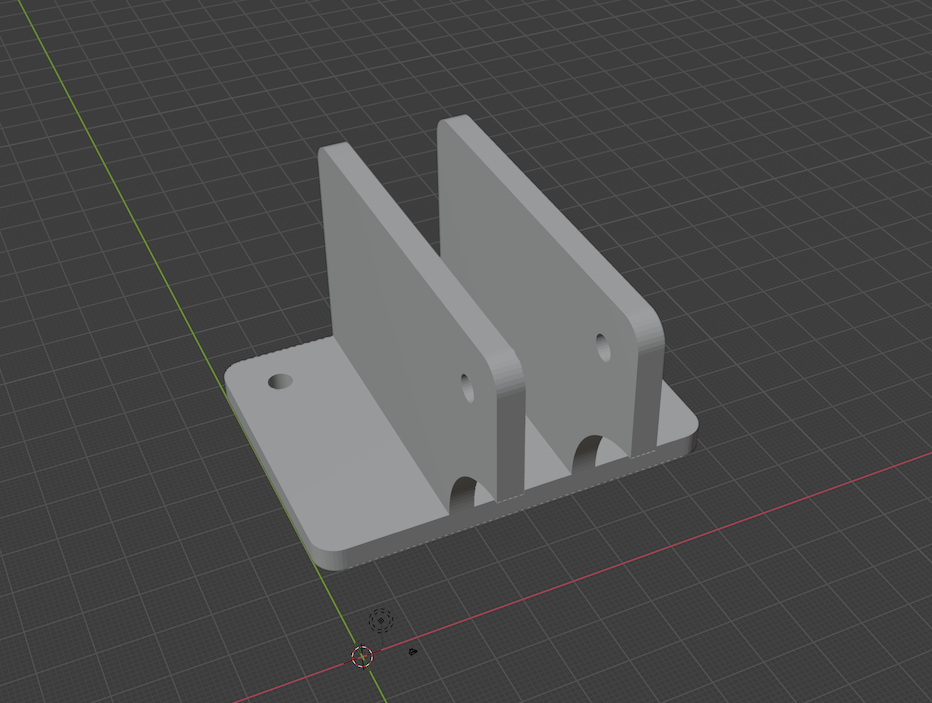 |
 |
counterweight_idler_1.blend | counterweight_idler_1.stl | 1 | printed |
| counterweight idler 2 | 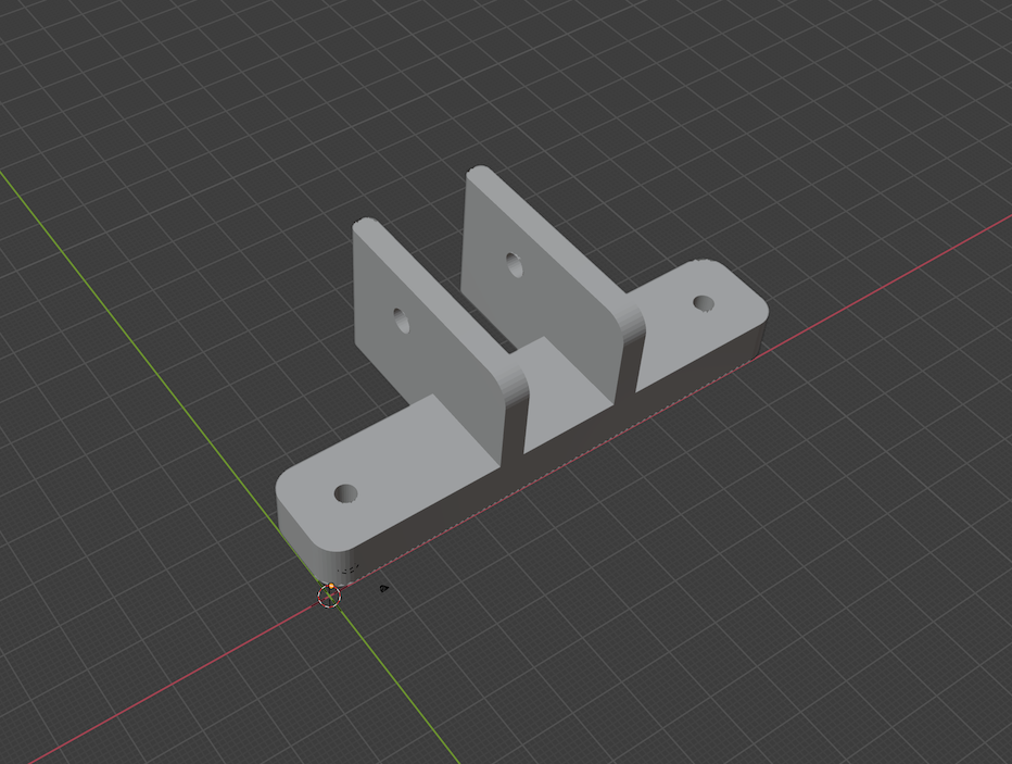 |
 |
counterweight_idler_2.blend | counterweight_idler_2.stl | 1 | printed |
| counterweight idler 2 r2 | 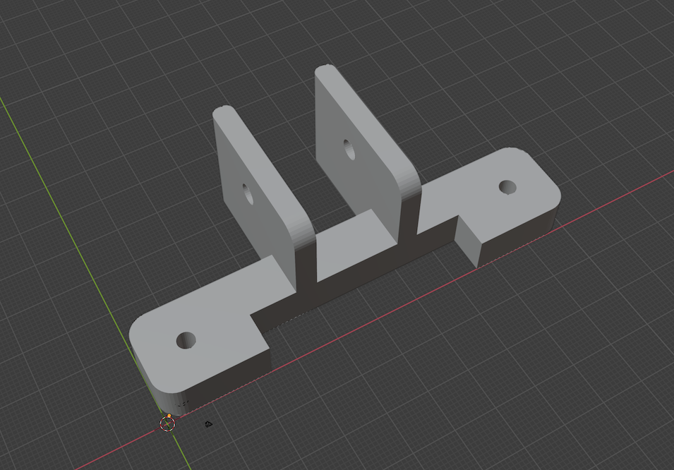 |
 |
counterweight_idler_2_r2.blend | counterweight_idler_2_r2.stl | 1 | printed, to clear stepper mount r2 |
| solid state relay clamp | 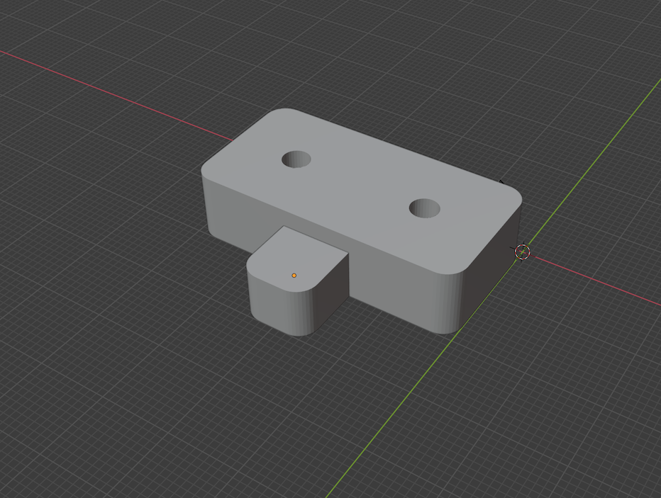 |
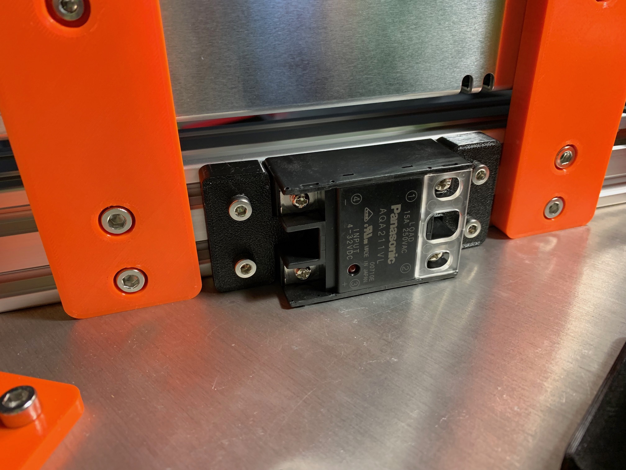 |
ssr_clamp.blend | ssr_clamp.stl | 2 | printed |
| extruder plate | 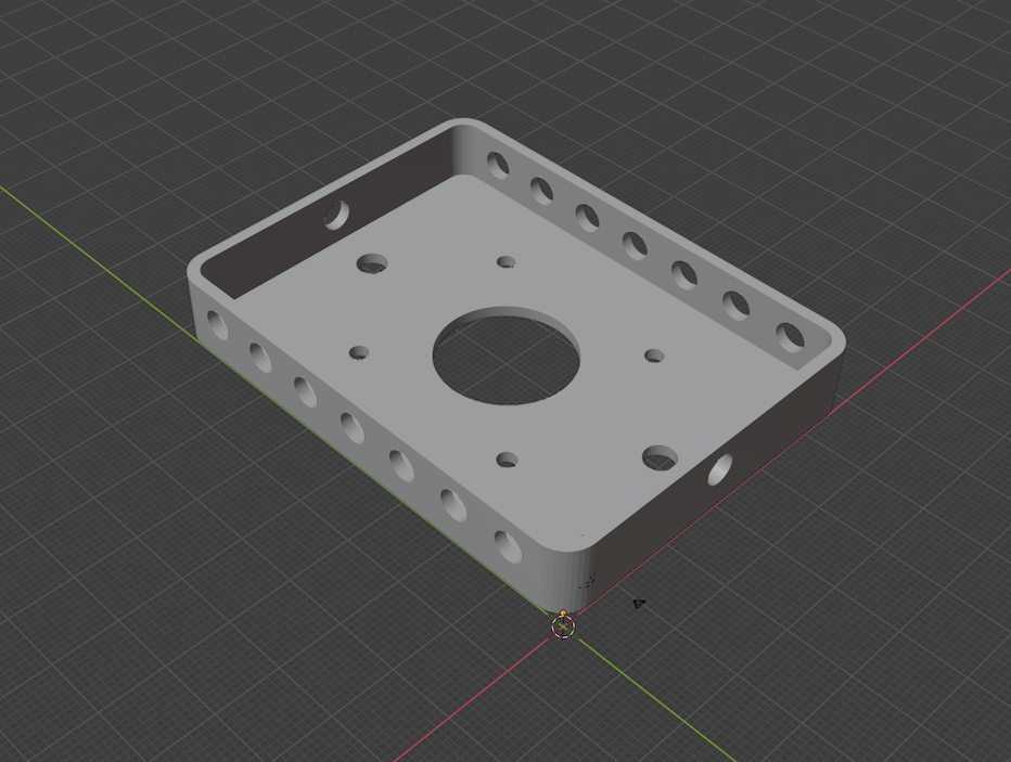 |
 |
extruder_plate.blend | extruder_plate.stl | 1 | printed, sandwich plate thickness maintains 100% contact between gears |
| simple fan duct | 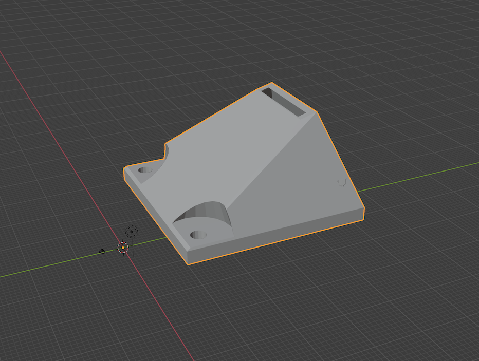 |
 |
Thingiverse dc42 CC | 40mm_fan_duct_v6_v0.3.stl | 1 | printed, opening trimmed with a razor, definitely Berd-air curious at this point |
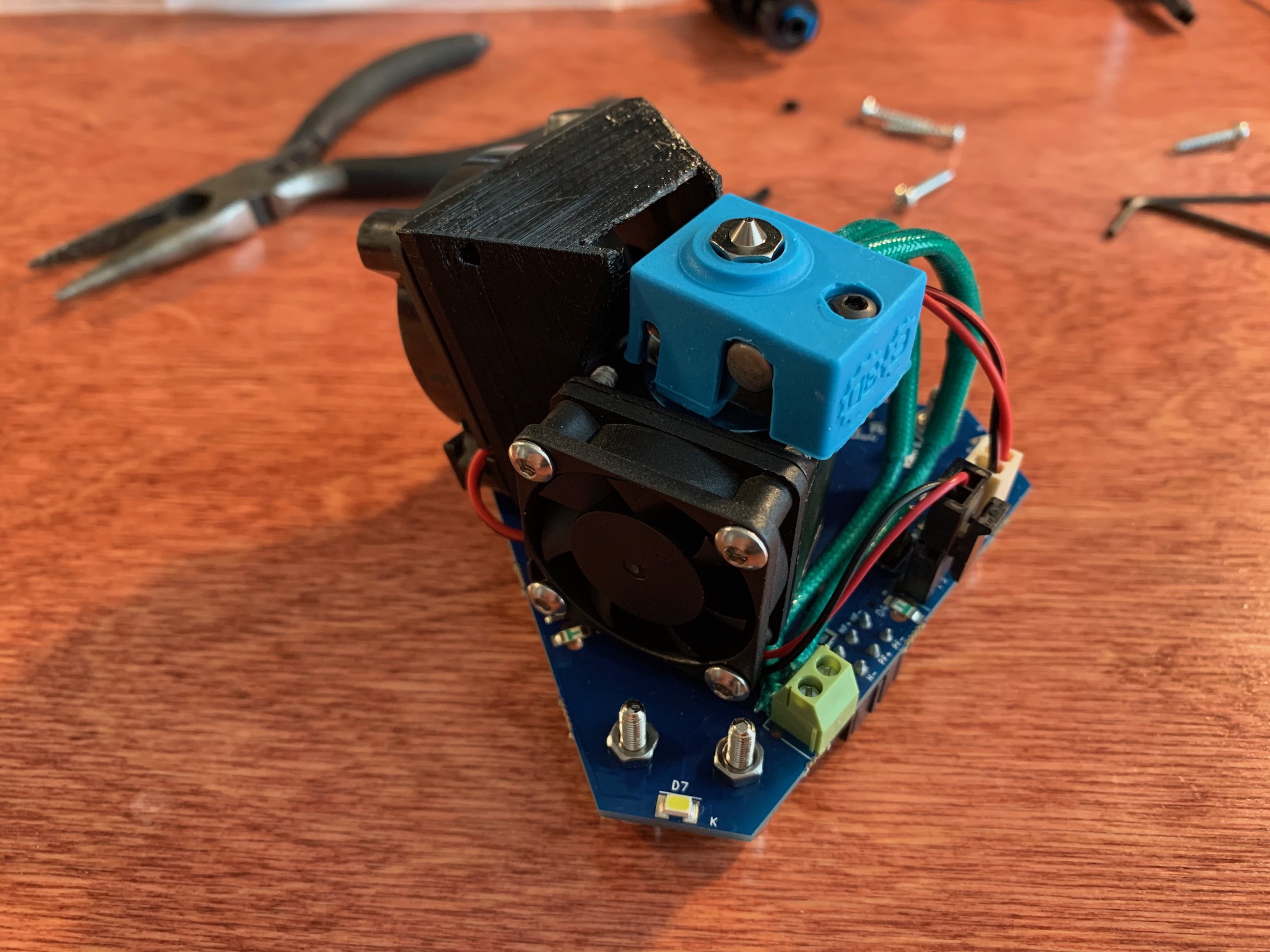
| effector fan bracket | 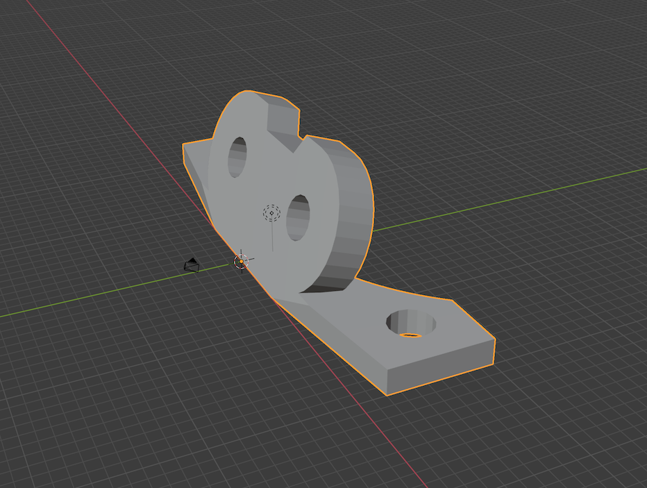 |
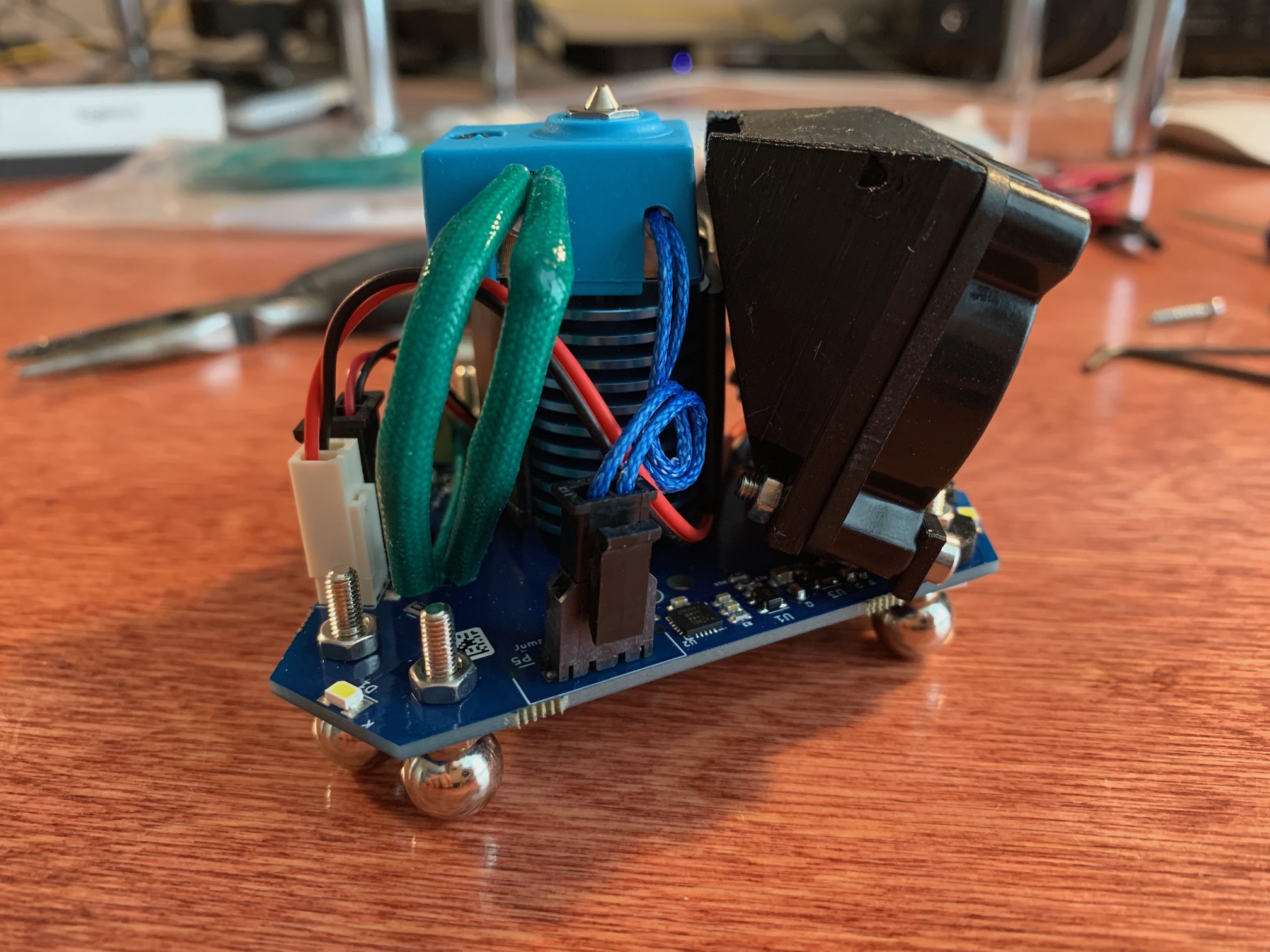 |
Thingiverse dc42 CC | EffectorFanBracket.stl | 1 | printed, may want to brace the duct to the heat sinc if using high accelerations |
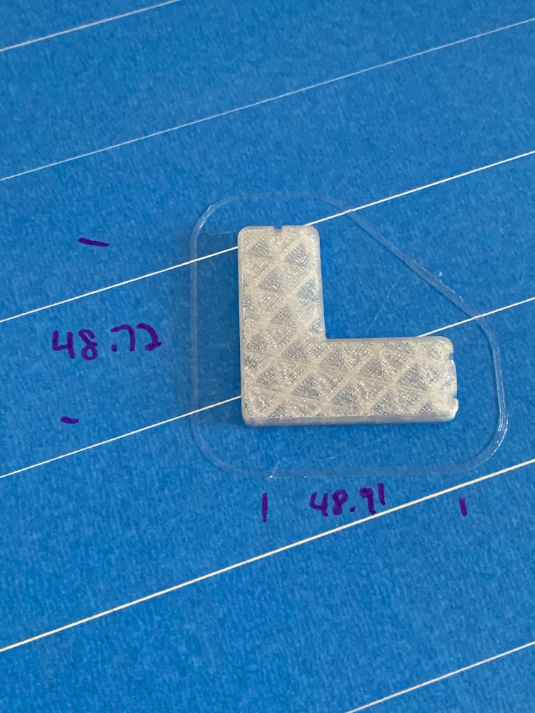
| build plate spacer | build_plate_spacer.blend | build_plate_spacer.stl | 3 | printed in HTPLA, then heat treated | ||
| spool tower ends | 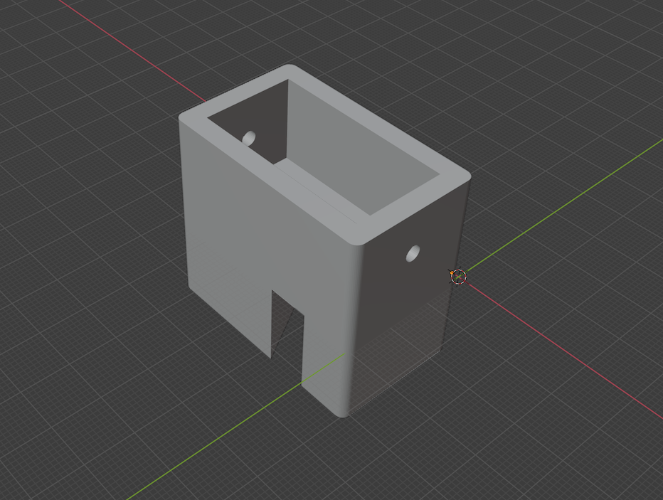 |
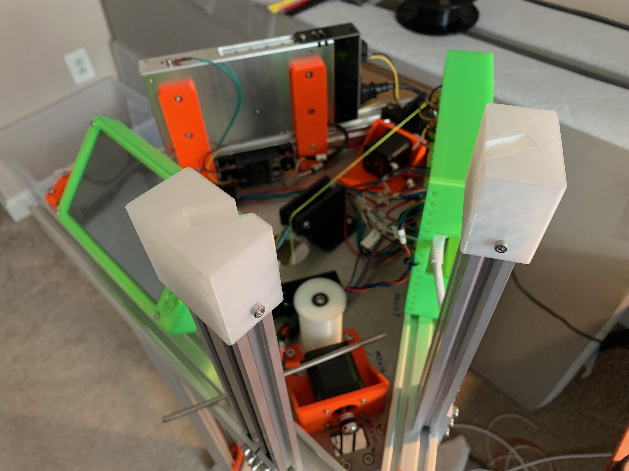 |
spool_tower_ends.blend | spool_tower_ends.stl | 2 | printed, print one mirrored |
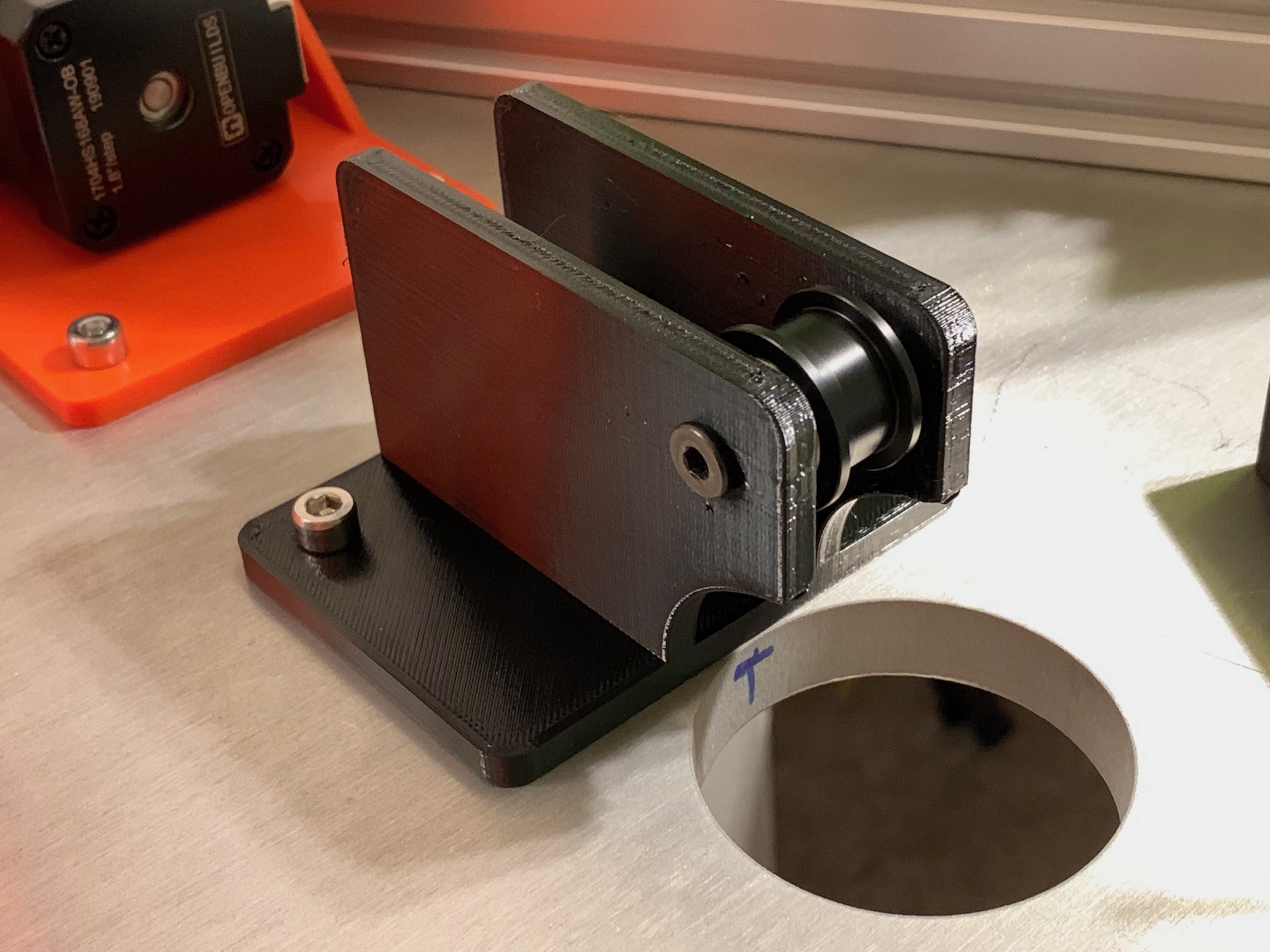
| spool bearing shaft | 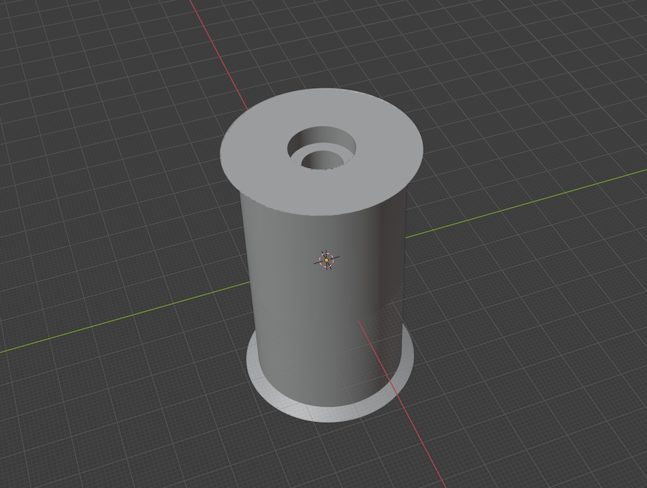 |
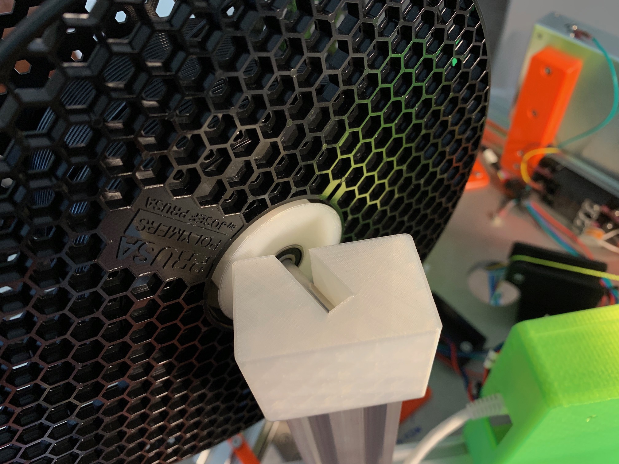 |
spool_bearing_shaft.blend | spool_bearing_shaft.stl | 1 | printed |
| buck converter case | 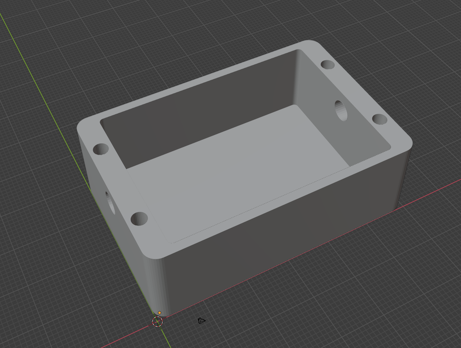 |
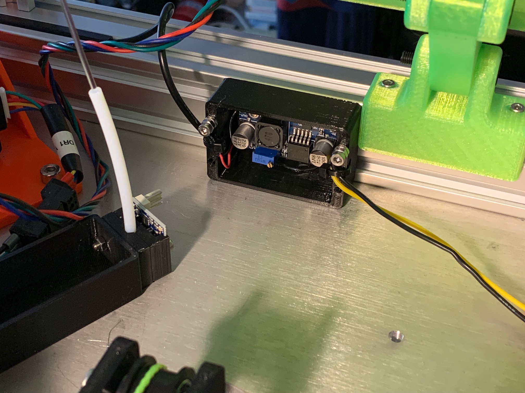 |
buck_case.blend | buck_case.stl | 1 | printed, dab of E6000 glue holds the DC-DC buck converter in |
| belt tensioner plate | 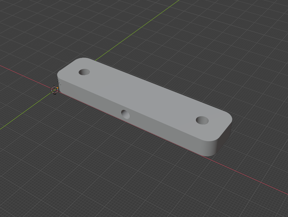 |
 |
tensioner_plate.blend | tensioner_plate.stl | 3 | printed, to help get the belts tigher than just pushing down by hand, and to make it easy to get the belts to the same tension |
| build plate wedge | 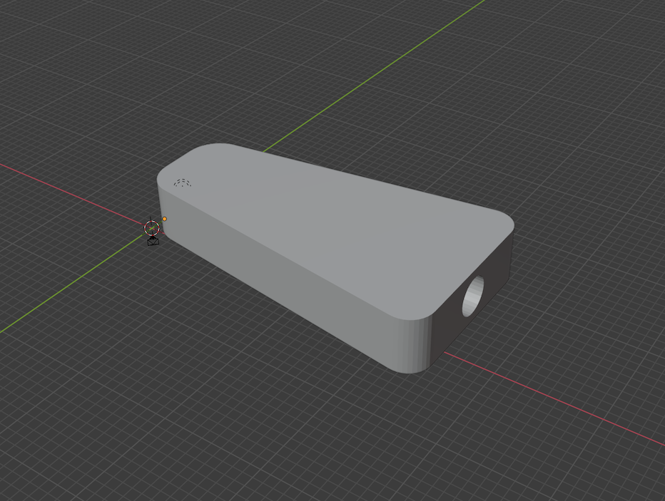 |
 |
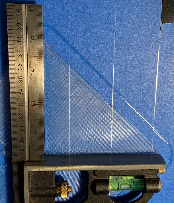
build_plate_wedge.blend | build_plate_wedge.stl | 6 | printed in HTPLA, then heat treated |
| filament sensor front | 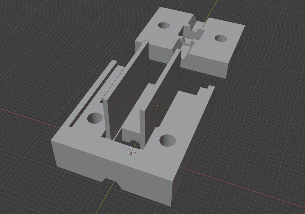 |
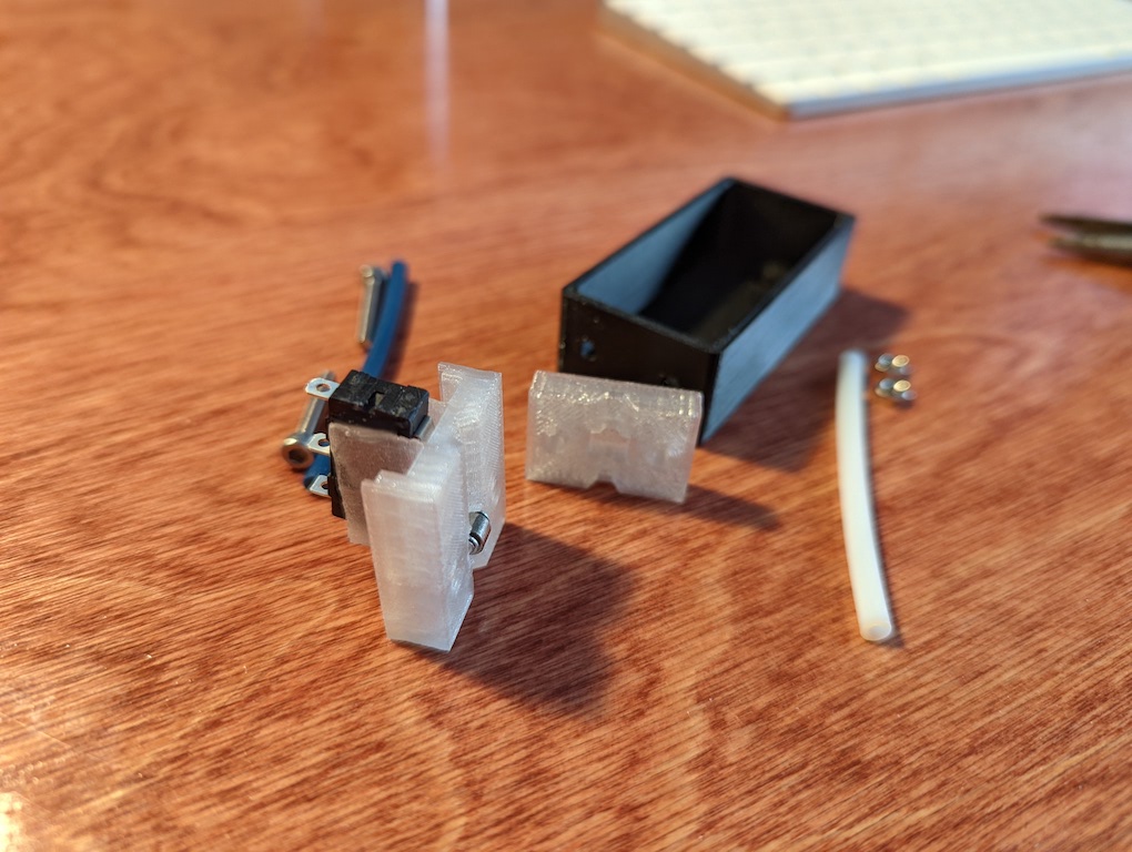 |
filament_sensor.blend | filament_sensor_front.stl | 1 | printed, based on Duet3D/DC42 laser filament monitor housing |
| filament sensor back | 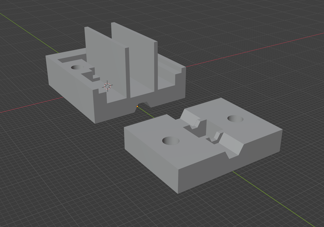 |
 |
filament_sensor.blend | filament_sensor_back.stl | 1 | printed, based on Duet3D/DC42 laser filament monitor housing |
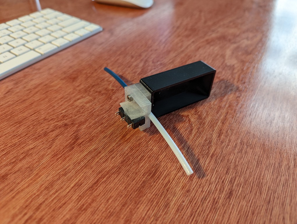
| filament sensor holder | 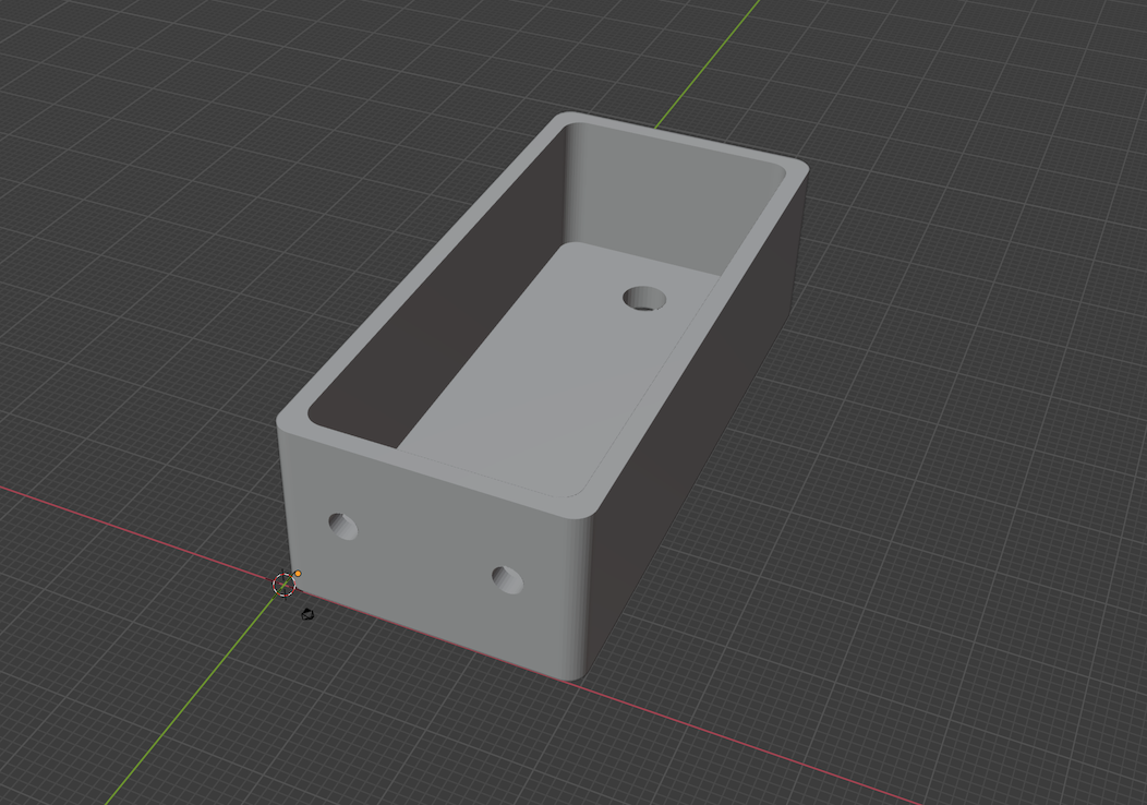 |
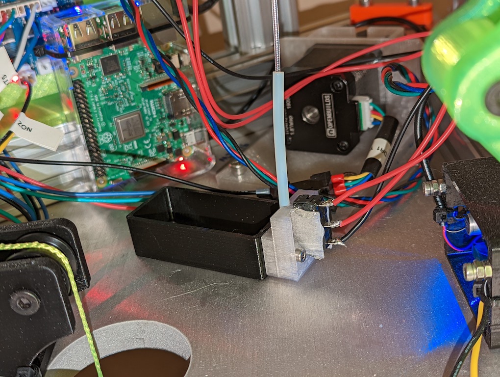 |
filament_sensor_holder.blend | filament_sensor_holder.stl | 1 | printed, holds the sensor PTFE tube in line with a frame plate hole |
I considered three different extruder options:
I considered a counterweight in all cases, especially the flying extruder.
Each approach has pros and cons. The flying extruder approach is quite proven and it does well with fast printing, but it can struggle with retraction speed and flexible filaments if the bowden tube is too long. The direct drive approach excels with quick, accurate retractions and it can handle flexible filaments, but that adds mass to the effector and it significantly reduces acceleration. The remote direct drive approach seems like the best of both worlds, but the Nimble Flex is currently in preorder and I'm not sure how well the flexible driveshaft angles will work in an enclosure.
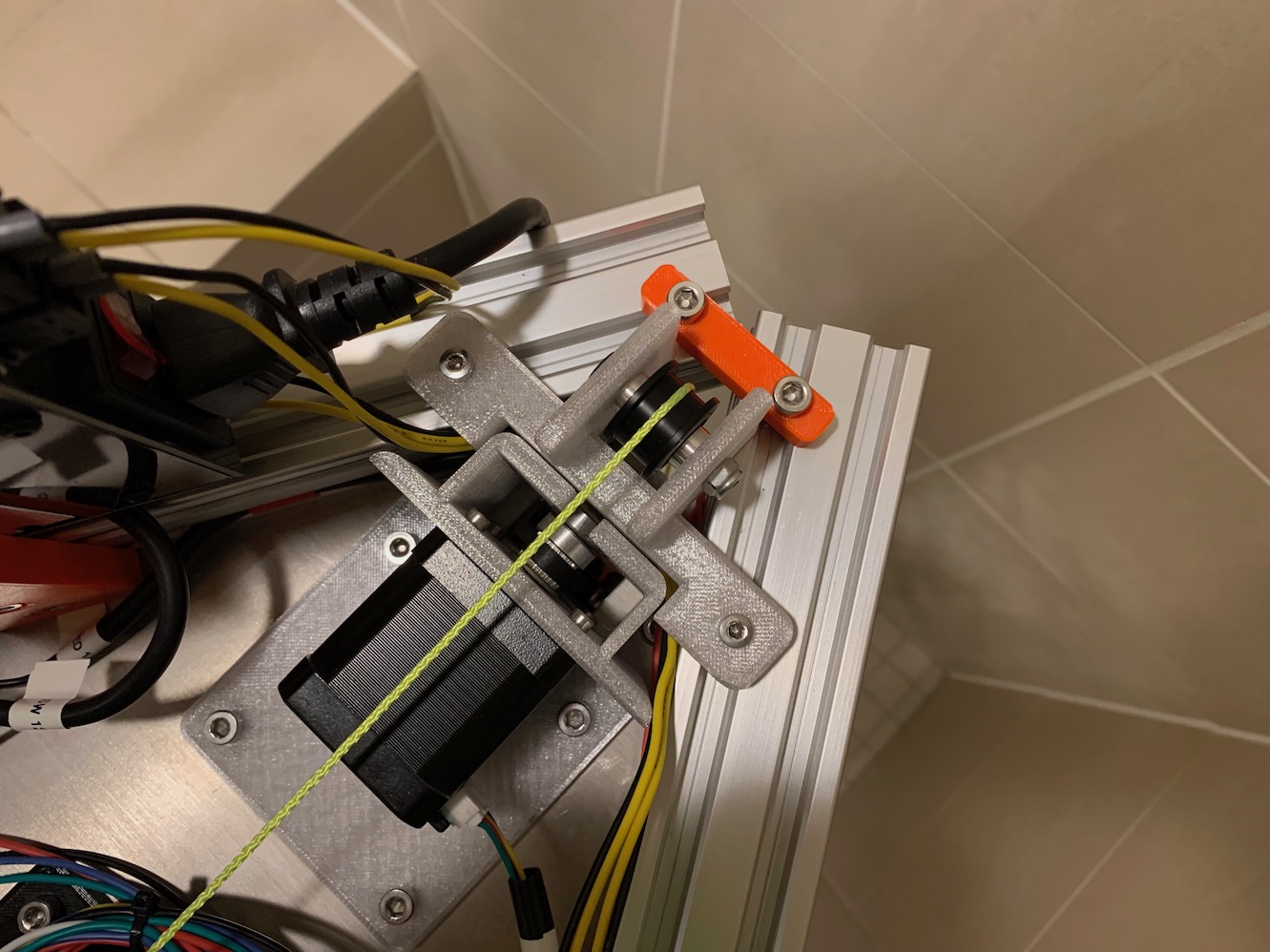
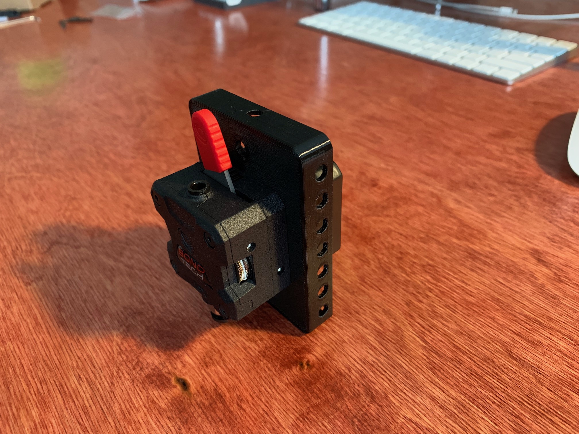
So the approach I'm choosing initially is the flying extruder with the Bondtech LGX.
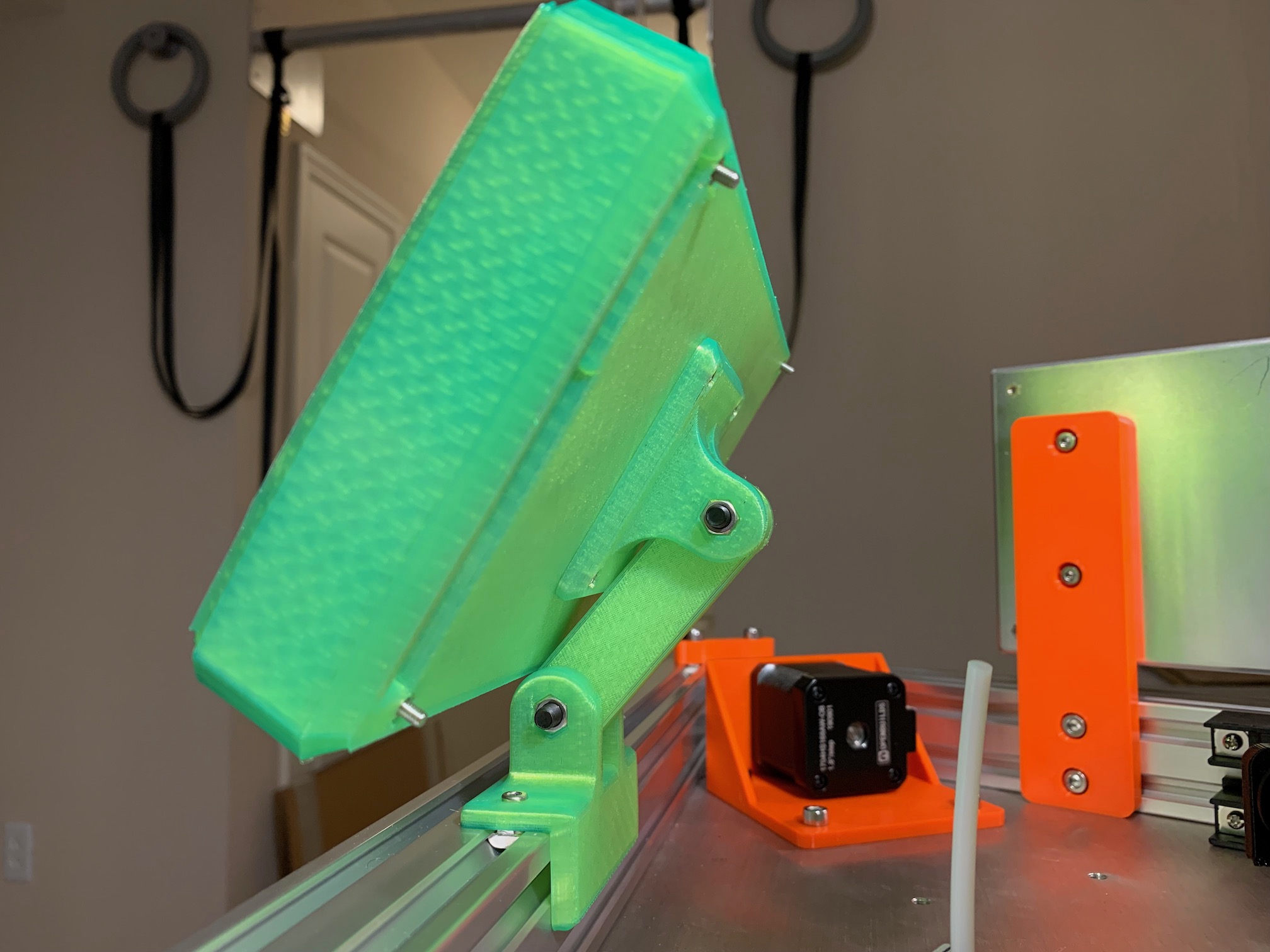
The 100% infill solid counterweight gantry roughly balances the extruder and extruder plate. Pulley, wheel, and bearing friction is enough to hold that assembly in place wherever it is stopped. In motion, things settle in the gantry direction a little, so it is slightly heavier than the extruder alone. With just that amount of counterweight, the bowden tube pushes the extruder up during positive Z moves. For fast Z moves, the weight of the extruder may fall to the flexible shock cord attached to the c-beam gantry plates, which are supposed to be for centering. In order to keep some tension on the extruder and bowden tube, and to offset some of the effector and carriage weight, I added 400g to the counterweight gantry.
After attaching wiring and the bowden tube, I disconnected the timing belts to do some weight measurements. I placed a scale on the build plate under the centerd nozzle. With no counterweight, I measured 1137g at the nozzle, which includes c-beam gantry plates, delta arms, wiring, extruder, and effector. With counterweight gantry + 400g, I measured 497g at the nozzle. Each tower stepper is still holding up some weight, but less. I've seen a couple other builds using this counterweight approach, but I haven't done a ton of research. And I definitely haven't seen a detailed discussion of the counterweight mass.
config-20220220.zip is the latest. Currently working:
I started by using the RepRapFirmware Configuration Tool, then slowly iterating and making customizations/tweaks. I must say the RRF documentation and tech articles are pretty good. I was able to get things up and running without scouring forums or asking for help. I really like being able to fully configure the firmware with config files; no recompilation or flashing necessary.
I initially started with rough estimates/assumptions and the RRF delta auto calibration/compensation. For delta rod/arm length, I used 400mm since they were made for that bearing center-to-center distance. For delta radius, I homed and centered the towers, then measured the rod angle with my phone. A little SOHCAHTOA trigonometry later and I had an estimate for the delta radius, which is the holizontal distance betweeen bearing centers. I followed the documentation for calibrating a delta and the online configuration tool, which recommended a 6-point 6-factor auto calibration/compensation. This got pretty close. Some test prints looked good and they had some reasonably accurate length dimensions.
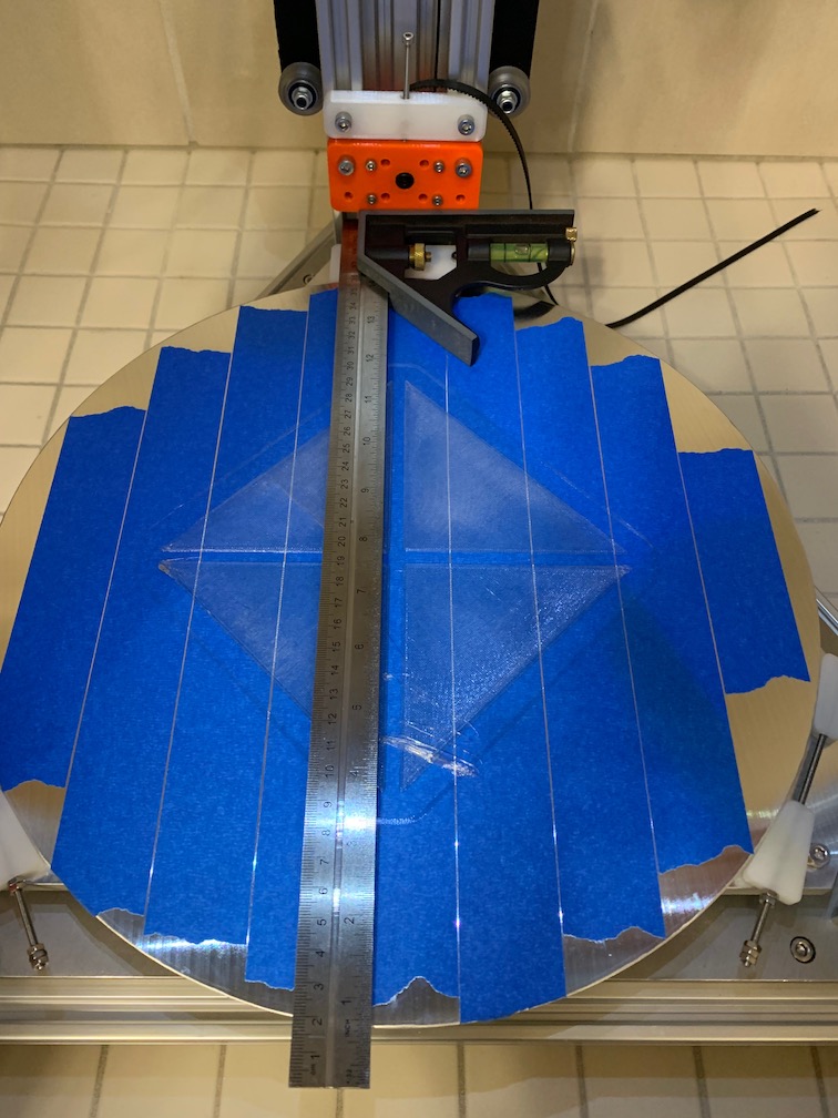
After a bunch of useful smaller prints, I needed to do a larger print and use more of the build plate. This showed a definite problem. X and Y lengths were pretty accurate, but there was clearly skew. Y was not square to the tower and the parts were not square, but it wasn't bad enough that I noticed on smaller prints.
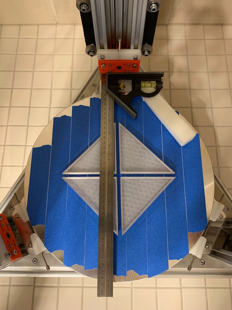
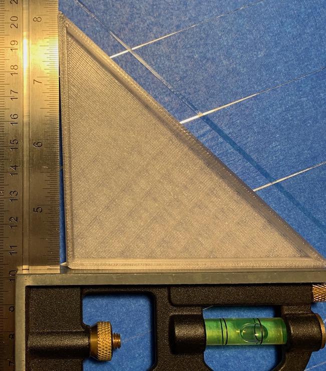
I did a whole bunch of head scratching and I reviewed the pages for Calibrating a delta printer and Configuring RepRapFirmware for a Linear Delta printer. All of this got me thinking the skew was being introduced by insufficient auto calibration/compensation. I realized I was probably not using enough auto calibration bed probe points and probably not spaced out far enough. But I wasn't looking forward to redoing and expanding calibration points or manually measuring offsets. I saw "you may need to run auto calibration two or three times before the corrections converge." Then I saw "if your printer is accurately built, then 4-factor calibration may be sufficient." The point about an accurate build needing less calibration made me realize a perfectly accurate build and perfect measurements would render auto calibration unnecessary. My build is pretty accurate, with waterjet cut plates, nice rails, and quality components. So I decided to try replacing the delta auto calibration with a single center bed Z probe and mesh bed leveling. This change immediately squared things up, but lengths were off a bit.
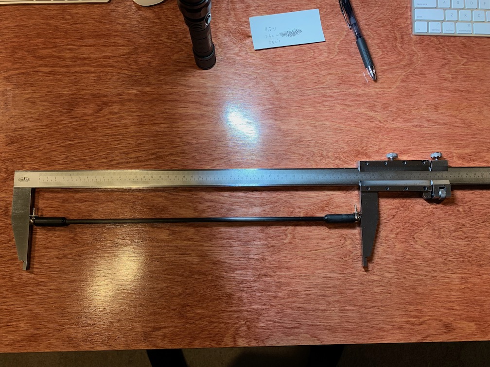
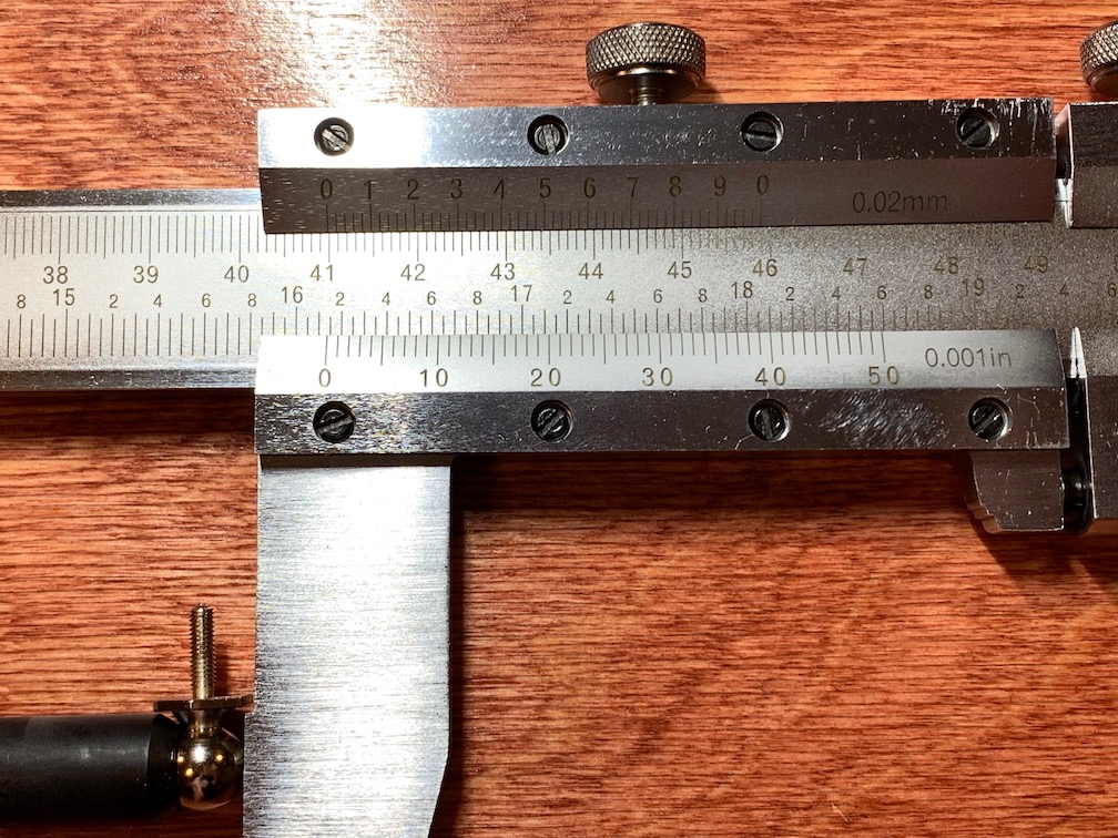
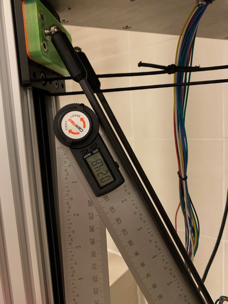
This improvement was encouraging. I came across M579 for the ~2.5% X/Y scaling errors I was seeing. That worked on a small test print, but it seemed like too much of a fudge factor. I thought better measurements for delta rod legnth and delta radius might correct printed length while still keeping things square. I got a hilariously huge vernier caliper to accurately measure delta rod length, best bang for the buck. I got a digital protractor to accurately measure the rod angle, for a better delta radius calculation. I averaged a few rod + 2 magball lengths, then subtracted average magball diameter to get average rod bearing center-to-center length. I used a tower spacer and the protractor to get homed rod angle. Then I used SOH, with angle and rod length, to calculate the delta radius. These more accurate measurements for M665 made my parts much more accurate, with no scaling factors, and still square. A 200mm diameter test cylinder showed just 0.35% oversize on the diameter.
While I was reading about RRF configuration, I saw that some features are not compatible with the attached SBC configuration. That configuration runs Duet Web Control on the Raspberry Pi instead of on the Duet3 mainboard. The thought seems to be that offloads some processing from the mainboard to the Pi as well as providing wireless access. But some feedback necessary for some features isn't available over a remote gcode-only interface. Everything seemed to run fine with the SD card in the mainboard and testing over wired ethernet. I decided to use a Pi just for wireless netoworking for maximum feature compatibility. The Pi to Duet3 connection is ethernet. Several differnet approaches work.
The first approach I tried used an ssh tunnel. The drawback is you need to ssh from the client to the Pi before browsing to DWC. This worked fine for connecting from the wireless network to the wired Pi-Duet3 network.
The second approach I tried used a tcp relay/proxy. Various utilities like ncat, nc, etc. can be used to listen one interface and relay that connection elsewhere. This also worked fine.
The third approach I tried used the Pi as a WiFi->Ethernet router. This is a bit different from how most people route with the Pi. This requires your client computer to be aware that the Pi is a router to the DERPNET, which can be accomplished with static routes or home network/router configuration. This works great and it has very low overhead on the Pi, since it's just routing packets. Future improvement may include a webcam for print monitoring. And all of the GPIO pin headers are still available, unlike the attached SBC approach. This seems to be the most robust and most seamless approach, so this is what I chose.
I chose Raspberry Pi OS Lite, since this is a headless configuration with no monitor. I configured WiFi and sshd on the SD card. After booting, I configured ethernet and iptables/NAT.
Several resources were helpful for setting up the Pi the way I wanted.
The Pi hostname is set to derppi.local. The Pi wlan0 is configured for dhcp, so it gets its IP address from my home network WiFi router. The Pi eth0 is configured for static ip, with 192.168.35.10 and no gateway or dns. The Duet3 mainboard is configured for static ip, with 192.168.35.50. I configured my home network router to provide a static DHCP lease to the derppi. I configured my home network router with a static route to the DERPNET via the derppi IP address. This allows any WiFi client on my home network to access IPs on the DERPNET without any special client configuration.
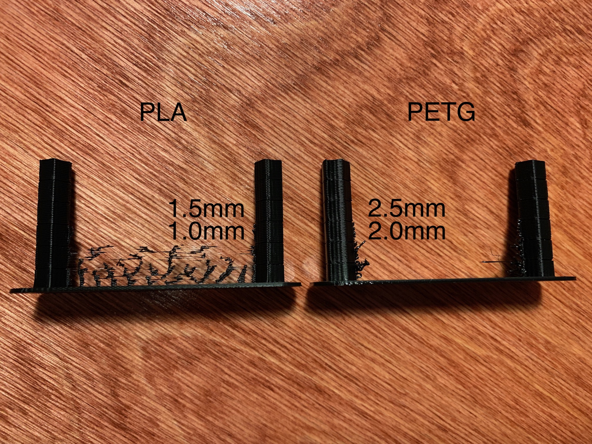
I used the Teaching Tech 3D Printer Calibration GitHub page to generate some retraction test tower gcode. I had to tweak it slightly in a text editor for my liking, but this was very helpful. My initial 1st layer testing and test prints used 5mm retraction in the slicer as a hopefully safe initial value. But these towers show usable values are closer to 1.5mm for PLA and 2.5mm for PETG. I'll need to repeat this sort of testing whenever I make significant changes, try new filament types, etc.
I'm using PrusaSlicer because I'm already comfortable with it, it's open source, and it has worked pretty well with my first printer. Figuring out how to add a new printer and associated profiles wasn't the most intuitive, but it didn't take too long either. After adding a new printer in the configuration wizard, I ended up copying existing Prusa filament profiles and Prusa print settings to new profiles and settings. Then I was able to edit them and associate them with the DERP printer. It seems the built-in profiles and settings are marked read-only and they are associated with the Prusa printers, which prevents using them unmodified with another printer. That was a minor hurdle and learning curve, but no big deal.
These initial settings are pretty conservative, but they were good enough for my first few good prints. It will take some testing, calibration, and hardware/firmware tweaking to increase speed and quality.
Here is the latest exported slicer config: PrusaSlicer_config_bundle_20220126.ini
I noticed some more belt stretch with the 5mm Open Builds GT2 belts, which contributed to a couple sub-par prints. Things cleaned up after another thumb belt tensioning. After a bunch of good prints, I ended up with a third broken belt, another ruined overnight print, and some broken effector parts and wires. This was with the improved stepper mounts, so things were nice and square. I'm thinking this was due to two factors: under-size belts and slight rubbing on the frame plate. I had already moved the frame plate belt cutout 3mm toward the center in CAD, but my frame plates need some milling to correct my initial design.
I didn't want to be without a printer while fixing and updating the DERP. So I picked up a Flsun V400 from my local Micro Center. It's like a slightly smaller and more mature DERP. It's superior in some ways and inferior in other ways. I'll use it to print varous projects and parts while I'm working on the DERP 3550 R2.